
An Ultimate Guide to Rotary Encoder [Working Principle, All Types Explained, Terminology, Glossary, Pros And Cons]

The increase of factory automation and the growing demand for electronic position sensing tools across different industries bring a rise in the number of encoder devices used and is mainly causing the growth of rotary encoders.
An increase in demand for rotary encoders in the automotive industry and the rising trend of industrial automation are among the cases expected to direct the growth of the market for rotary encoders.
A rotary encoder is a type of position sensor that measures the mechanical movement and displacement and converts it into an output signal. The purpose of an encoder is to provide feedback about the speed, direction, or position of a mechanical device to control systems.
Rotary encoders are the most frequently used configuration of encoders that are designed in two main forms including the absolute encoder and the incremental encoder. They are widely used in different applications which need monitoring or control of mechanical systems.
In this article, we will review the rotary encoder as well as its different types. Also, we provide a basic understanding of the construction, and working principle, of the rotary encoder. Apart from all this, we present information about the applications, advantages, and disadvantages of a rotary encoder.
To be used in an application Encoders have 3 forms which help the operators to install them to the system. You can click the link below to see all Encoder products.
Let’s see how does an Encoder work?
Shaft Encoder
A shaft encoder is an electromechanical sensor device that can be connected mechanically to a rotating motor shaft and electrically attached to a logic system in order to track the current position of a motor shaft and report information about its rotation angle to the logic system.
Shaft rotary encoders come with a rod that helps with attachment to the application. Also they use couplings to get fixed in the system.
Shaft encoders are used in various mechanical applications such as robotic applications, computer mice, and industrial controls. They are also frequently used in machine tool changers, camera lenses, and telescopes.

Hollow Encoder
A hollow encoder is one of the most commonly used designs that are much more versatile. Instead of using a solid mechanical shaft to couple the motor, a hollow shaft encoder directly mounts to the motor shaft and is clamped in place. It’s attached in position by using a flexible tether.
Therefore, a hollow encoder does not need to be completely sized to fit the motor and it does not require any flexible parts which increase its size.
Also, forgiving installation is another feature of a hollow encoder that reduces shaft load. A hollow encoder eliminates shocks and vibrations on mechanical shaft couplers which would cause misalignment and then provide a non-repeatable angular reading. A hollow shaft encoder provides reliable performance that is ideal for industrial duty applications.

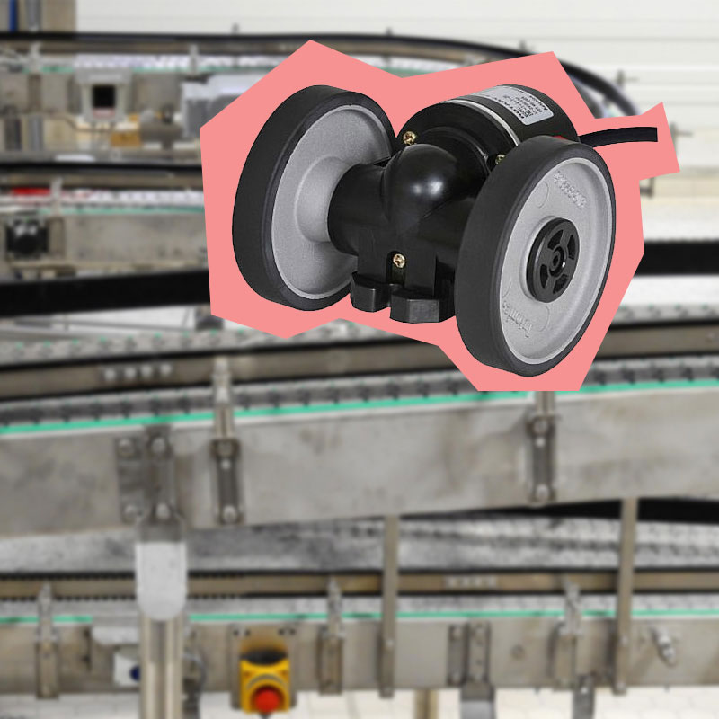
Wheel Type
A wheel encoder is a type of sensor that is placed directly behind each motor. It is used to count the number of times the motor (left or right) has turned.
This can be used to determine the distance that the robot has driven or turned. A wheel encoder is commonly made of two parts: A Hall Effect sensor that is used to determine the strength of a magnetic field and a ring magnet (similar to a metal washer) connected to the motor shaft. Once the motor turns the wheel, it also turns the ring magnet. When the ring rotates, the Hall effect sensor placed near the ring detects changes in the magnetic field. So the sensor can count the number of times the motor has rotated.
In an encoder with a measuring wheel, the application is not restricted by the length of the scale, and it provides indefinite measurement in one direction without the need to back in the other direction.
Wheel encoders are suitable for measuring the length, distance traveled, speed, and correct differences in motor speeds of constantly moving objects in production-line environments.
Wheels type encoders are essential optical components in every industrial and commercial design. The circumference of the measuring wheel is corresponding to the PPR of the encoder and the surface material of the wheel determines the traction with the target being measured. So, both these specifications are necessary for achieving optimal accuracy during measurement.
Learn more about encoder in explained: Rotary Encoder [Working principle, Types, Applications, Features] article. In case you’d like to check wheel type encoder products, click the link bellow.
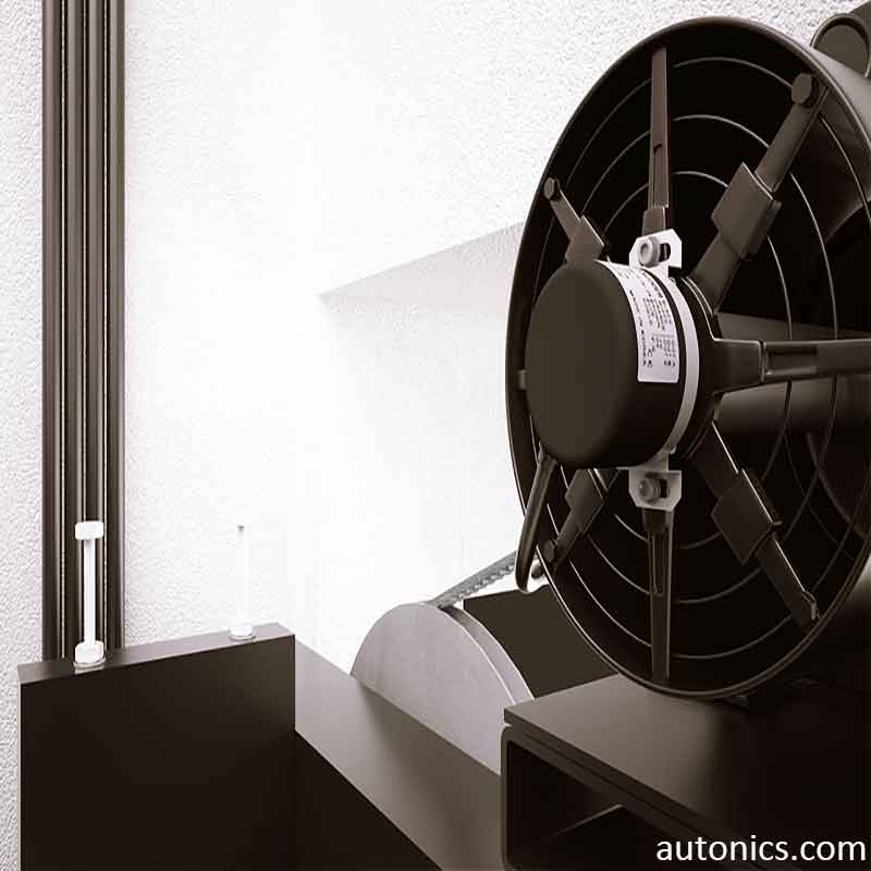
Selected Applications From Factory Automation Industry
Rotary Encoder Working Principle
A rotary encoder contains a disk that is connected to a shaft. There are contact zones on the disk that are equally slotted.
The disk is attached to the common ground pin C and two other separate contact pins A and B.
When the disk turns step by step, pins A and B comes in contact with the common pin and produce the two square wave output signals in a specific order according to the turning direction.
When one pin comes in contact with the other pin, the output signals are displaced 90° out of phase with each other.
When the encoder is turning clockwise, first the A pin connects and then followed by the B pin. If we count the pulses of the output signal, the rotation position can be determined.
Also, to determine the turning direction of the encoder, we need to track when each pin connects to and disconnects from the ground, and consider these signal changes at the same time. It can be done by easily observing the state of B when A changes state.
Rotary Encoder Types
There are various ways in which rotary encoders can be divided for motion control applications. The most important classification is based on their working principle. Here we have the three most common types that are the following:
• Incremental encoder
• absolute encoder
• Linear encoder
Incremental Encoder
The incremental encoder is one of the common type used to measure the position and speed of a system.
Incremental encoder operates by reading changes in angular position instead of reading an absolute angle of the encoded shaft and also It resets each time the power supply is removed.
The encoder transforms the rotational motion or position of a shaft into electrical impulses through an optical disk that determines the direction and angle of rotation.
Incremental rotary encoders produce an output signal each time the shaft rotates a certain angle. The number of signals (pulses) per turn determines the resolution of the device.
An incremental encoder generates 2 output signals, called “A” and “B” to sense position. These 2 signals are set up 90° out of phase, which is needed for the detection of the encoder’s rotation. By turning the encoder in the clockwise direction, the “A” pulse leads the “B” pulse, by turning the shaft counterclockwise direction, the “B” pulse leads the “A” pulse. So both the position and direction of rotation can be determined by monitoring the number of pulses and the relative phase of signals A and B.
Additionally, some incremental encoders include a “Z” signal that is used for the accurate determination of a reference position. There are optical, magnetic, and mechanical versions of incremental encoders.
In Incremental encoder (Working Principle, Types, Applications, Advantages) article you can know much more about this type.
To see Incremental Encoder products click the link bellow.

Absolute Encoder
Absolute rotary encoders, or angular rotation sensors, measure the absolute angle of rotation of a machine’s shaft.
They determine the absolute angle directly from the start-up and maintain the last value recorded if the power supply is removed from the encoder.
Unlike incremental encoders that generate a continuous stream of pulses, absolute encoders generate unique digital words or bits for each angle position. For absolute encoders, the resolution is usually defined as the number of measurement bits per revolution. Where accuracy for both speed and position is needed, this type of encoder is the best choice.
There are single-turn and multi-turn variations of absolute encoders. Single-turn encoders measure the position within one full revolution, 360°, with the output signal repeating for every revolution of the shaft.
Multi-turn encoders not only measure position within a single turn but also contain an additional “turns” counter that determines the number of revolutions. Multi-turn encoders are suitable for lengthy or complex positioning-based applications.
Absolute Encoder (Working Principle, Types, Applications, Advantages) article will give a complete guide about absolute encoders.

Linear Encoder
Other than angular moves, encoders can measure linear moves of a mechanism without making any contact.
They generate position feedback in the form of electrical signals. The encoder consists of an encoder-head and a linear scale and can measure the speed, distance, direction, and displacement of a target that moves along linear axes.
Linear Encoders are commonly available in two types, absolute and incremental, and are explained by their position signals.

The sensor of the linear encoder detects the scale that encodes a position and transforms the information into a digital or analog signal. Then, this signal can be decoded by a proper motion controller into position.
The sensing technology of linear encoders should be optical or magnetic. Linear encoders are well suited for use in linear systems and many various applications ranging from automated assembly machines to x-ray equipment. In Linear Encoder (Types, Applications, Advantages) article we will tell you much more please follow the link.

Rotary Encoder Terminology
Resolution
Resolution is a measure that refers to the number of output pulses while the rotary encoder shaft turns once. For the incremental rotary encoder, the resolution is defined as the number of measuring segments per revolution on silt, and for the absolute rotary encoder, resolution designates the number of divisions.
Starting torque
At the start of the rotation, the torque is required to turn the shaft of the rotary encoder. The starting torque is usually slightly greater than the torque during rotation.
Maximum response frequency
The max. number of output pulses per second that the rotary encoder could respond to electronically. And also it is the speed of the shaft during the operation of the device in which the encoder is used.
Note: • Max. revolutions are within max. allowable revolutions.
• Resolution should not pass the max. response frequency.
Maximum allowable revolution (rpm)
Mechanical specification
It is defined as the mechanical maximum permissible revolution of a rotary encoder and affects the operation life of the encoder. So, please do not go over the rated values listed.
Maximum response revolution (rpm)
Electronic specification
The maximum revolution speed for the rotary encoder to generate an electric signal normally. It is determined by max. response frequency and resolution.
Note: Max. revolutions are within max. permissible revolutions. Resolution should not pass max. response frequency.
CW (Clockwise)
The rotational direction of the encoder shaft in clockwise. (A phase leads to B phase at 90° in our company's standard feature.)
CCW (Counter-clockwise)
The rotational direction of the encoder shaft in the counterclockwise shaft. (B phase leads to A phase at 90° in our company's standard feature.)
A, B phase
A and B are Digital signals that the difference between these phases as an electrical angle is normally 90° and is used to determine the rotation direction.
Z phase
Z or zero-reference phase is a Signal that is made once a revolution.
BCD Code (Binary-Coded Decimal code)
It is a binary numbering decimal system. it has a wide range of applications in controllers and counters due to it easily changing a decimal code to a binary code with the '8 4 2 1' that represents the weight of each bit,
For example, for converting decimal digit 23 to binary-coded decimal code, it would be done;
Binary code
The most basic code represented in a symbol system combination of 0 and 1.
For example, decimal digit 27 to binary code is 11011.
Gray code
Gray code is produced to complete the errors of binary code. Only one bit alters the state from one position to another so that it avoids the occurrence of errors.
For example, in the case of converting decimal digit 12 (1100 in binary code) to gray code, it is 1010.
Glossary (Coupling)
Misalignment
Parallel misalignment
When the centers of two axes attached by a coupling are asymmetric, it turns with parallel misalignment by δ.
Angular misalignment (Symmetrical)
If the center distances of two axes attached by a coupling are equal, it turns with angular misalignment by α.
Angular misalignment (Non-symmetrical)
If the center distances of two axes attached by a coupling are unequal, it turns with angular misalignment by α.
Combined parallel and angular misalignment
If the centers of two axes attached by a coupling are unparalleled, it turns with parallel misalignment by δ and angular misalignment by α.
End-play
It turns with End-play by X from one of two shafts attached by a coupling.
Run out
It turns with vibration in a radial direction.
Advantages and Disadvantages of Rotary Encoder
Advantages
• Rugged and hard-wearing to suit different applications
• High resolution
• Compact design
• Long service life and long-distance range
• Low weight and low inertia
• Resistant to dust and magnetism
• Suitable for parameters that have a large range of adjustment
• Highly reliable and accurate
• Less-cost feedback
• Integrated electronics
• Fuses optical and digital technology
• Can be integrated into existing applications
• The output is controlled based on the rotational displacement of the shaft
Disadvantages
• Exposed to magnetic or radio interference
• Interference of direct light source
• Sensitivity to dirt, oil, and dust contaminates
Rotary Encoder Application
• Robotics, CNC machines, and the printing industry
• Control Servo Motor
• Woodworking, metalworking equipment, grain storage, linear motors
• In automation for storage and transportation system
• Metallurgical industry
• Green energy area
• Packaging
• Food and beverage
• Textiles
• Mechanical engineering, the conveyor industry
• Automated guided vehicles (AGVs) and horticulture
• Brushless DC motors
• Door control devices
• Lens beveling machines
• Plotters
• Cut-to-length applications
• Testing machines
• Ultrasonic welding
• Filling applications
• Warping machines and medical-technical equipment
• Parts assembly machines
• Ball Screw Positioning
• Labeling machines
• Graphical displays of X and Y axes
• Analysis systems
• Drilling machines
• Mixing machines
• Indication systems
• PLC systems & PCs in industries
• Mobile vehicle
• Aerospace
• Material Handling
• Lift Industry
• Assembly Machines
• CNC Machines
• Motor Feedback