

Revving Up Precision: Exploring the World of Wheel Encoders
Imagine you're driving a car on a winding road and need to maintain a consistent speed and position. You rely on the feedback from your car's speedometer and odometer to ensure you're staying on track. Similarly, machines and robots rely on sensors to measure speed and position, and one such sensor that plays a vital role in this process is the wheel encoder. A wheel encoder is a device that measures the rotation of a wheel and translates it into digital signals that can be used by machines to accurately measure speed and position. With applications in robotics, automation, and even the automotive industry, wheel encoders are a crucial component in modern machinery
What is an encoder?
An industrial encoder is a type of sensor that is used in various industrial applications to measure the position, velocity, and/or acceleration of rotating machinery, such as motors, gears, and conveyor systems.
Industrial encoders are typically installed on the rotating shaft of the machinery, and they generate electrical signals that are proportional to the rotation of the shaft. These signals can be used by control systems to monitor the speed and position of the machinery and to make adjustments or trigger alarms based on this information.
Different Types of Encoders
There are two main types of encoders: absolute encoders and incremental encoders.
Absolute Encoder
Absolute encoders provide a unique code or position value for each position within the encoder's range. This means that the encoder can report the exact position of the shaft or object being monitored, even if it is moved or rotated when the power is off. Absolute encoders can be single-turn or multi-turn. Single-turn encoders provide a unique code for each position within a single revolution of the shaft, while multi-turn encoders can track multiple revolutions of the shaft. Absolute encoders are commonly used in applications where precise positioning is critical, such as in robotics, CNC machines, and medical equipment.
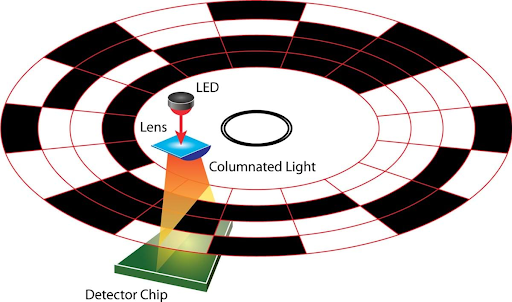
Fig 1. How absolute encoder works
Discover now: go deeper into the world of absolute encoder by finding out how they work, where they are used and what pros they bring in!
Incremental Encoder
Incremental encoders generate a series of pulses that are used to track the movement of the shaft or object being monitored. Each pulse corresponds to a small movement of the shaft, and the direction of rotation can be determined by the order in which the pulses are generated. Incremental encoders do not provide absolute position information and require a reference point to determine the actual position. They are commonly used in applications where speed and relative position are more important than absolute position, such as in motion control systems, servo motors, and automated manufacturing equipment.
Both absolute and incremental encoders can be further classified based on the type of output signal they provide. These include linear encoders, rotary encoders, magnetic encoders, optical encoders, and more. The choice of encoder type and output signal depends on the specific requirements of the application.
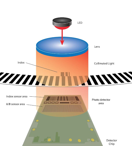
Fig 2. How incremental encoders work
Don’t miss out on one of our popular blog posts: what incremental encoders are, how they work and in what applications you can use them.
Encoder Types Based on Output Signal
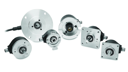
Fig 3. Different types of encoder
Linear Encoders
Linear encoders are used to measure linear position or distance. They consist of a scale and a read head, with the scale being a stationary bar or tape that is marked with a pattern of lines or dots. The read head contains a sensor that detects the lines or dots on the scale and generates a signal that is proportional to the position of the scale. Linear encoders can be either absolute or incremental and can use various technologies such as optical, magnetic, or inductive sensing.
Rotary Encoders
Rotary encoders are used to measure rotary position or angle. They consist of a disc or ring that is marked with a pattern of lines or dots, and a read head that contains a sensor that detects the lines or dots on the disc or ring and generates a signal that is proportional to the position of the disc or ring. Rotary encoders can be either absolute or incremental and can use various technologies such as optical, magnetic, or capacitive sensing.
Read more: what are different types of encoders? How do they work? Where are they used? Find your answers here!
Magnetic Encoders
Magnetic encoders use magnetic fields to detect the position of a shaft or object being monitored. They consist of a magnetized disc or ring and a read head that contains a sensor that detects changes in the magnetic field as the disc or ring rotates. Magnetic encoders can be either absolute or incremental, and are highly resistant to environmental factors such as dirt, oil, and vibration.
Optical Encoders
Optical encoders use light to detect the position of a shaft or object being monitored. They consist of a disc or ring that is marked with a pattern of lines or dots, a read head that contains a light source, and a sensor that detects changes in the light as the disc or ring rotates. Optical encoders can be either absolute or incremental are highly precise and can provide high-resolution position information.
Capacitive Encoders
Capacitive encoders use changes in capacitance to detect the position of a shaft or object being monitored. They consist of a disc or ring that is marked with a pattern of conductive lines or dots, and a read head that contains two or more electrodes that detect changes in capacitance as the disc or ring rotates. Capacitive encoders can be either absolute or incremental are highly accurate, and can be used in high-speed applications.
Inductive Encoders
Inductive encoders use changes in inductance to detect the position of a shaft or object being monitored. They consist of a disc or ring that is marked with a pattern of conductive lines or dots, and a read head that contains a coil that generates a magnetic field that induces changes in inductance as the disc or ring rotates. Inductive encoders are typically incremental, and are highly resistant to environmental factors such as dirt, oil, and vibration.
Hybrid encoders can combine two or more types of encoder technology to provide specific performance characteristics. For example, a magnetic-optical encoder might use magnetic sensing for rough position detection and optical sensing for fine position detection. The choice of encoder type depends on the specific requirements of the application, including accuracy, resolution, environmental conditions, and speed.
What is a Wheel Encoder?
A wheel encoder is a device used to measure the rotation or angular position of a wheel or shaft. It typically consists of a wheel with evenly spaced slots or holes around its circumference and a sensor that detects the passing of the slots or holes as the wheel rotates.
When the wheel rotates, the sensor generates electrical signals that can be processed to determine the direction and speed of the rotation. Wheel encoders are commonly used in robotics, automation, and control systems where precise control of wheel position and velocity is required. They are also used in navigation systems, such as GPS receivers, to measure the distance traveled and track the movement of vehicles.
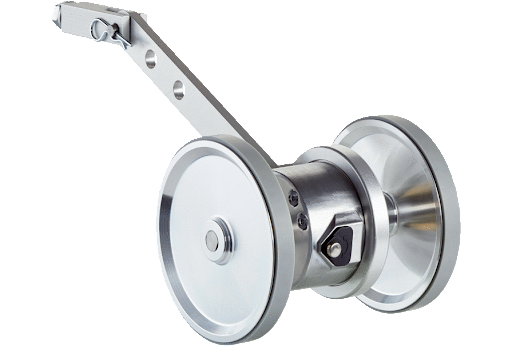
Fig 4. Wheel encoder
How Many Types Does a Wheel Encoder Have?
A wheel encoder typically has two types:
- Optical wheel encoder: An optical wheel encoder uses a light source and a photodetector to detect the slots or holes on the wheel as it rotates.
- Magnetic wheel encoder: A magnetic wheel encoder uses a magnetic field and a sensor to detect changes in the magnetic field caused by the slots or holes on the wheel as it rotates.
Both types of wheel encoders have their advantages and disadvantages, and the choice of which one to use depends on the specific application requirements. Optical encoders are generally more precise and offer higher resolution, but they can be affected by dirt or other contaminants on the wheel. Magnetic encoders, on the other hand, are more robust and can operate in harsher environments, but they may be less accurate and have lower resolution.
What is the Main Difference Between the Optical Wheel Encoder and the Magnetic Wheel Encoder?
The main difference between an optical wheel encoder and a magnetic wheel encoder is the technology used to detect the rotation of the wheel.
An optical wheel encoder uses a light source and a photodetector to detect the slots or holes in the wheel as it rotates. The light source shines through the slots or holes, and the photodetector measures the intensity of the light. By analyzing the changes in the intensity of the light, the encoder can determine the position and speed of the wheel.
In contrast, a magnetic wheel encoder uses a magnetic field and a sensor to detect changes in the magnetic field caused by the slots or holes on the wheel as it rotates. The magnetic field can be generated by a magnetized wheel or a separate magnetic disc attached to the wheel. As the wheel rotates, the changes in the magnetic field are detected by the sensor, which can then be used to determine the position and speed of the wheel.
There are some differences between optical and magnetic encoders in terms of their performance and suitability for different applications. Optical encoders generally offer higher resolution and accuracy than magnetic encoders, but they may be more sensitive to dust and other contaminants. Magnetic encoders are more robust and can operate in harsher environments, but they may have lower resolution and be more susceptible to electromagnetic interference. The choice of which type of encoder to use depends on the specific requirements of the application.
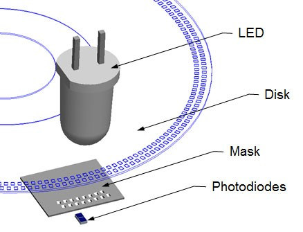
Fig 5. An optical wheel encoder
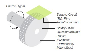
Fig 6. A magnetic wheel encoder
Wheel Encoder Working Principle
Wheel encoders are a type of rotary encoder that measures the rotation of a wheel or shaft. They work on the principle of incremental encoding, meaning that they generate a series of pulses that correspond to the rotation of the wheel or shaft.
Wheel encoders consist of a wheel with slots or holes and a sensor that detects the slots or holes as the wheel rotates. The sensor may be optical or magnetic depending on the specific type of encoder.
In an optical wheel encoder, the wheel has a series of slots or holes that are detected by a light-emitting diode (LED) and a photodiode. As the wheel rotates, the slots or holes pass between the LED and photodiode, causing changes in the amount of light that is detected. The changes in light are converted into electrical signals that correspond to the rotation of the wheel.
In a magnetic wheel encoder, the wheel has a series of magnets that are detected by a magnetic sensor. As the wheel rotates, the magnets pass by the sensor, causing changes in the magnetic field. The changes in the magnetic field are converted into electrical signals that correspond to the rotation of the wheel.
The electrical signals generated by the wheel encoder are typically in the form of square waves, with each pulse corresponding to a specific amount of rotation. The number of pulses generated per rotation is determined by the number of slots, holes, magnets, or conductive elements on the wheel, and the resolution of the encoder is determined by the number of pulses per rotation.
The graphic below outlines the basic construction of an incremental rotary encoder using optical technology. A beam of light emitted from an LED passes through the Code Disk, which is patterned with opaque lines (much like the spokes on a bike wheel). As the encoder shaft rotates, the light beam from the LED is interrupted by the opaque lines on the Code Disk before being picked up by the Photodetector Assembly. This produces a pulse signal: light = on; no light = off. The signal is sent to the counter or controller, which will then send the signal to produce the desired function.
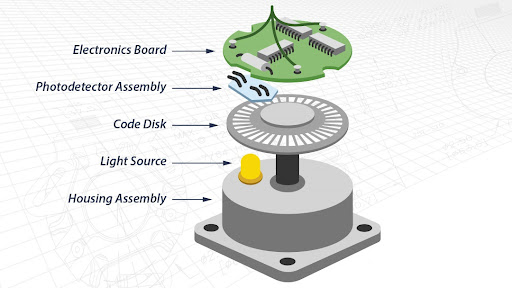
Fig 7. The basic construction of an incremental rotary encoder
Different Parts of Wheel Encoder
The structure of a wheel encoder can vary depending on the specific type and manufacturer, but the basic components are similar. A wheel encoder typically consists of the following parts:
1.Wheel: The wheel is the rotating component that contains the slots or holes that the encoder uses to measure the rotation or angular position. The wheel can be made of plastic, metal, or other materials depending on the application requirements.
2.Encoder disk: The encoder disk is a slotted disk that is mounted on the wheel. It can be made of metal or plastic and is used to detect the rotation of the wheel.
3.Sensor: The sensor is the component that detects the movement of the slots or holes on the encoder disk. For optical encoders, the sensor is typically a photodetector that measures the intensity of the light passing through the slots or holes. For magnetic encoders, the sensor is typically a Hall effect sensor that detects changes in the magnetic field caused by the slots or holes.
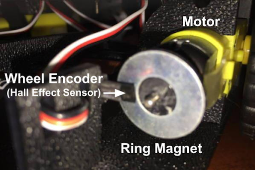
Fig 8. The wheel encoder in the industry
4.Circuit board: The circuit board is the component that processes the signals from the sensor and generates the output signals. It can also contain other components, such as an amplifier, signal conditioning circuitry, and a microcontroller.
5.Housing: The housing is the protective enclosure that contains the wheel, encoder disk, sensor, and circuit board. It can be made of plastic or metal and is designed to protect internal components from dust, moisture, and other contaminants.
6.Connectors: The connectors are the components that provide electrical connections between the encoder and the rest of the system. They can be a variety of types, including pins, wires, or cables with various connector types.
Overall, the structure of a wheel encoder is designed to accurately measure the rotation or angular position of a wheel or shaft and provide the output signals necessary for control or measurement purposes.
What are the Basic Formulas for a Wheel Encoder?
The formula for the wheel encoder depends on what you are trying to calculate. Here are some common formulas used for wheel encoders:
Distance Traveled
If you know the number of encoder pulses and the circumference of the wheel, you can calculate the distance traveled by the wheel using the following formula: Distance Traveled = Number of Encoder Pulses x Circumference of Wheel / Number of Pulses per Revolution
Speed
If you know the time it takes for a certain number of encoder pulses to occur, you can calculate the speed of the wheel using the following formula: Speed = Number of Encoder Pulses / Time
Encoder Resolution
The encoder resolution is the number of pulses per revolution of the encoder. You can calculate the encoder resolution using the following formula: Encoder Resolution = Number of Encoder Pulses / Number of Wheel Revolutions
Encoder Accuracy
The encoder accuracy is the difference between the actual position of the wheel and the position reported by the encoder. You can calculate the encoder accuracy using the following formula: Encoder Accuracy = | Actual Position - Reported Position |
Note that the actual formulas used for wheel encoders may vary depending on the specific type of encoder and the application.
An example of using these formulas:
Let's say we have a wheel encoder with 500 pulses per revolution and a wheel with a circumference of 0.5 meters. We want to know how far the wheel travels and how fast it is moving based on the encoder readings.
Distance Traveled
Let's say the encoder records 1000 pulses.
We can use the formula: Distance Traveled = Number of Encoder Pulses x Circumference of Wheel / Number of Pulses per Revolution
Distance Traveled = 1000 x 0.5 / 500
- Distance Traveled = 1 meterSo the wheel has traveled 1 meter based on the encoder readings.
Speed
Let's say it takes 2 seconds for the encoder to record 100 pulses.
We can use the formula: Speed = Number of Encoder Pulses / Time
Speed = 100 / 2
- Speed = 50 meters per secondSo the wheel is moving at a speed of 50 meters per second based on the encoder readings.
Note that these calculations are just examples and the actual values may vary depending on the specific setup and application.
How can we Choose a Right Wheel Encoder?
Choosing the right wheel encoder for a specific application depends on several factors, including the required resolution, accuracy, speed, and environmental conditions. Here are some factors to consider when selecting a wheel encoder:
1.Type of encoder: Decide whether you need an optical or magnetic encoder based on your application requirements. Optical encoders offer higher resolution and accuracy but may be sensitive to dust and contaminants. Magnetic encoders are more robust and can operate in harsher environments but may have lower resolution and accuracy.
2.Resolution: Determine the required resolution of the encoder. This refers to the number of pulses or steps per revolution of the wheel. The higher the resolution, the more accurate the measurement. The unit of resolution in industrial encoders is typically given in counts per revolution (CPR) or lines per revolution (LPR).
CPR refers to the number of distinct position points that can be detected within one complete rotation of the encoder shaft. For example, an encoder with 1000 CPR can detect 1000 unique positions within one full rotation.
LPR is similar to CPR but refers specifically to the number of lines or marks on the encoder disk or tape. For example, an encoder with 5000 LPR would have 5000 distinct lines or marks on the encoder disk or tape.
The resolution of an encoder is important because it determines the accuracy of the position measurement. A higher resolution encoder will provide more precise position information, allowing for more precise control of the system being monitored or controlled.
1.Speed: Consider the maximum speed of the wheel and select an encoder with a suitable maximum operating speed.
2.Environmental conditions: Consider the temperature range, humidity, and other environmental conditions in which the encoder will operate. Choose an encoder that can operate reliably in those conditions.
3.Electrical interface: Consider the electrical interface of the encoder, such as the output signal type (analog or digital), voltage level, and connector type. Make sure it is compatible with your system's requirements.
4.Mounting and shaft size: Consider the mounting and shaft size of the encoder to ensure it can be easily installed and fits with your system's wheel or shaft.
5.Cost: Consider the cost of the encoder and choose one that fits within your budget while meeting your application requirements.
By considering these factors, you can select the right wheel encoder for your specific application.
Does a wheel Encoder Need Calibration?
Yes, wheel encoders typically require calibration to ensure accurate and reliable operation. Calibration is the process of adjusting the encoder output signals to match the actual position or movement of the wheel.
Calibration is important because there may be slight variations in the encoder's output due to manufacturing tolerances, temperature fluctuations, or other environmental factors. By calibrating the encoder, you can correct for these variations and ensure accurate measurement and control.
The calibration process typically involves comparing the output signals of the encoder to a known reference, such as a laser interferometer or a mechanical gauge. The calibration can be performed during initial installation or periodically during operation to ensure continued accuracy.
Some wheel encoders come with built-in calibration features, such as calibration routines that can be initiated through software or hardware interfaces. Other encoders may require external calibration equipment or specialized software.
How can I Measure the Wheel Encoder's Accuracy?
To measure the accuracy of a wheel encoder, you can compare its output signals to a known reference signal or position. Here are some common methods for measuring wheel encoder accuracy:
- Laser Interferometer: A laser interferometer is a highly accurate instrument that can measure the position of a moving object within a fraction of a wavelength of light. By comparing the output signals of the wheel encoder to the laser interferometer, you can determine the accuracy of the encoder.
- Mechanical Gauge: A mechanical gauge, such as a dial indicator or a micrometer, can be used to measure the position of the wheel or shaft to a high degree of accuracy. By comparing the readings of the gauge to the output signals of the encoder, you can determine the accuracy of the encoder.
- High-resolution encoder: A higher-resolution encoder can be used as a reference to measure the accuracy of a lower-resolution encoder. By comparing the output signals of the two encoders, you can determine the accuracy of the lower-resolution encoder.
- Oscilloscope: An oscilloscope can be used to measure the output signals of the encoder and compare them to a known reference signal. By analyzing the waveform of the signals, you can determine the accuracy of the encoder.
The specific method used to measure the accuracy of a wheel encoder will depend on the application requirements and available equipment. In general, a combination of methods may be used to obtain the most accurate measurement of the encoder's performance.
What are the Wheel Encoder Applications?
Wheel encoders have a wide range of applications across various industries. Some common applications include:
- Robotics: Wheel encoders are used in robotics to measure the rotation or position of wheels, joints, or other moving parts. This information is used to control the movement and position of the robot.
- Automation: Wheel encoders are used in automated systems, such as conveyor belts, to measure the speed and position of moving parts. This information is used to control the operation of the system and ensure accuracy and efficiency.
- Motion Control: Wheel encoders are used in motion control systems to measure the speed and position of rotating shafts or motors. This information is used to control the motion of the system and ensure accuracy and precision.
- Automotive: Wheel encoders are used in automobiles to measure the speed and position of the wheels. This information is used for various functions such as anti-lock braking, traction control, and speedometer readings.
- Aerospace: Wheel encoders are used in aerospace applications, such as aircraft landing gear, to measure the position and movement of mechanical systems.
- Medical Devices: Wheel encoders are used in medical devices, such as surgical robots, to measure the position and movement of instruments and tools.
- Packaging: Wheel encoders are used in packaging equipment, such as filling machines, to measure the speed and position of moving parts. This information is used to control the operation of the equipment and ensure accurate filling and packaging.
Overall, wheel encoders are used in various applications that require accurate measurement and control of movement and position.
Fig 9. The wheel encoder in the industry
In which Industries Can I Use Wheel Encoders?
Wheel encoders can be used in a wide range of industries that require accurate measurement and control of movement and position. Some common industries that use wheel encoders include:
- Robotics: Wheel encoders are used in robotics to measure the rotation or position of wheels, joints, or other moving parts. This information is used to control the movement and position of the robot.
- Manufacturing and Automation: Wheel encoders are used in automated systems, such as conveyor belts and assembly lines, to measure the speed and position of moving parts. This information is used to control the operation of the system and ensure accuracy and efficiency.
- Motion Control: Wheel encoders are used in motion control systems, such as CNC machines and 3D printers, to measure the speed and position of rotating shafts or motors. This information is used to control the motion of the system and ensure accuracy and precision.
- Automotive: Wheel encoders are used in automobiles to measure the speed and position of the wheels. This information is used for various functions such as anti-lock braking, traction control, and speedometer readings.
- Aerospace: Wheel encoders are used in aerospace applications, such as aircraft landing gear, to measure the position and movement of mechanical systems.
- Medical Devices: Wheel encoders are used in medical devices, such as surgical robots, to measure the position and movement of instruments and tools.
- Packaging: Wheel encoders are used in packaging equipment, such as filling machines, to measure the speed and position of moving parts. This information is used to control the operation of the equipment and ensure accurate filling and packaging.
Overall, wheel encoders can be used in any industry that requires accurate measurement and control of movement and position.
Fig 10. Mouse Rotary Encoder
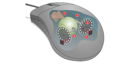
Fig 9. Mouse Rotary Encoder
What are the Wheel Encoder Advantages?
There are several advantages of using a wheel encoder:
- Accurate Position and Speed Measurement: Wheel encoders provide accurate position and speed measurements, which is critical in applications where precise control is required.
- Compact Size: Wheel encoders are typically small and lightweight, making them easy to install in a variety of applications.
- Low Cost: Wheel encoders are relatively low cost compared to other types of sensors, which makes them a cost-effective solution for many applications.
- Durability: Wheel encoders are designed to withstand harsh environments and can operate reliably in extreme temperatures, dust, and moisture.
- Easy to Install: Wheel encoders are easy to install and can be mounted directly on the shaft of a wheel or motor.
- Low Maintenance: Wheel encoders require little to no maintenance once installed, which reduces the overall cost of ownership.
- Versatility: Wheel encoders can be used in a wide range of applications, including robotics, automation, automotive, aerospace, and medical devices, among others.
What are the Wheel Encoder Limitations?
While wheel encoders have many advantages, they also have some disadvantages, including:
- Limited Resolution: The resolution of a wheel encoder is limited by the number of pulses per revolution, which may not be sufficient for some applications that require very precise measurements.
- Limited Range: Wheel encoders are limited in their range of measurement, and may not be suitable for applications that require measurement over long distances.
- Sensitivity to External Factors: Wheel encoders can be affected by external factors such as vibration, temperature changes, and electromagnetic interference, which can cause inaccuracies in the readings.
- Calibration: Some types of wheel encoders require calibration, which can be time-consuming and may require specialized equipment.
- Mechanical Wear: The physical contact between the wheel encoder and the surface it is measuring can cause mechanical wear over time, which can affect the accuracy of the readings.
- Integration: Wheel encoders may require additional hardware or software to integrate into a larger system, which can add complexity and cost.
What Does the Future of Wheel Encoders Look Like?
The future of wheel encoders is likely to involve further improvements in accuracy, durability, and miniaturization. Here are a few more specific potential developments:
- Integration with other sensors and technologies: As industrial automation systems become more complex and interconnected, there may be a need for wheel encoders to be integrated with other types of sensors or technologies. For example, encoders could be combined with accelerometers or gyroscopes to provide more complete position and motion data.
- Wireless communication: As wireless communication technology continues to improve, it may become possible for wheel encoders to transmit data wirelessly. This could eliminate the need for physical wiring between the encoder and the control system, making installation and maintenance easier and more flexible.
- Advanced signal processing: There may be opportunities to improve the accuracy and reliability of wheel encoders through advanced signal processing techniques. For example, using machine learning algorithms to analyze encoder data could help to identify and correct any errors or inaccuracies in the signal.
- Improved environmental resistance: Wheel encoders are often used in harsh environments where they may be exposed to dust, moisture, or extreme temperatures. Future encoders may be designed to be more resistant to these environmental factors, ensuring reliable performance even in challenging conditions.
Conclusion
In conclusion, a wheel encoder is a sensor that measures the position and speed of a rotating wheel. It works by generating a series of electrical pulses as the wheel rotates, which can be used to calculate the distance traveled and speed of the wheel. There are two main types of wheel encoders: optical and magnetic. Wheel encoders have many advantages, including accurate position and speed measurement, compact size, low cost, durability, easy installation, low maintenance, and versatility. However, they also have some disadvantages, such as limited resolution, sensitivity to external factors, mechanical wear, and the need for calibration in some cases. Overall, wheel encoders are useful sensors for a wide range of applications, from robotics and automation to automotive and medical devices.
To Recap
What is a wheel encoder?
A wheel encoder is a sensor that measures the position and speed of a rotating wheel.
What types of wheel encoders are there?
There are two main types of wheel encoders: optical and magnetic.
What are the advantages of using a wheel encoder?
The advantages of using a wheel encoder include accurate position and speed measurement, compact size, low cost, durability, easy installation, low maintenance, and versatility.
What are the disadvantages of using a wheel encoder?
The disadvantages of using a wheel encoder include limited resolution, sensitivity to external factors, mechanical wear, and the need for calibration in some cases.
How do you choose the right wheel encoder?
When choosing a wheel encoder, consider factors such as resolution, accuracy, speed range, temperature range, and the specific requirements of your application.
What are some common applications of wheel encoders?
Wheel encoders are commonly used in robotics, automation, automotive, aerospace, medical devices, and other applications where precise position and speed measurement is required.
Do wheel encoders require calibration?
Some types of wheel encoders may require calibration to ensure accurate measurements.
How can you measure the accuracy of a wheel encoder?
The accuracy of a wheel encoder can be measured by comparing its readings to a known standard or using a high-precision calibration device.
How are wheel encoders installed?
Wheel encoders are typically mounted directly on the shaft of the wheel or motor using a coupling or bracket.
What is the formula for calculating distance traveled using a wheel encoder?
The formula for calculating distance traveled using a wheel encoder is distance = (encoder counts / counts per revolution) x (wheel circumference).
Can a wheel encoder measure the direction of rotation?
No, a wheel encoder cannot measure the direction of rotation. It can only measure the position and speed of the rotating wheel.
What is the resolution of a wheel encoder?
The resolution of a wheel encoder is determined by the number of pulses per revolution. For example, an encoder with 1000 pulses per revolution will have a higher resolution than an encoder with 100 pulses per revolution.
Can a wheel encoder be used for linear motion?
A wheel encoder can be used for linear motion by mounting it on a linear slide or belt and pulley system.
What is the maximum speed that a wheel encoder can measure?
The maximum speed that a wheel encoder can measure depends on the specific encoder and the environment it is used in. Some encoders can measure speeds up to tens of thousands of revolutions per minute.
Can a wheel encoder be used in wet or dusty environments?
Yes, some wheel encoders are designed to be water-resistant and dust-resistant for use in harsh environments.
Can a wheel encoder be used with different wheel sizes?
Yes, a wheel encoder can be used with different wheel sizes as long as the circumference of the wheel is known and used in the distance calculation.
What is the difference between an incremental and an absolute wheel encoder?
An incremental encoder generates pulses as the wheel rotates, which are used to calculate the position and speed of the wheel relative to its starting position. An absolute encoder generates a unique code for each position of the wheel, allowing it to determine the absolute position of the wheel at any given time.
How do you connect a wheel encoder to a microcontroller or computer?
Most wheel encoders have output wires that can be connected to a microcontroller or computer using a suitable interface or signal conditioning circuit.
Can a wheel encoder be used for high-precision applications?
Yes, some wheel encoders are designed for high-precision applications and have very high resolution and accuracy.
What is the typical lifespan of a wheel encoder?
The typical lifespan of a wheel encoder depends on factors such as the type of encoder, the environment it is used in, and the amount of use it receives. Generally, most encoders can last for several years with proper maintenance and care.
References
images from:
https://www.encoder.com/article-what-is-an-encode...
https://www.usdigital.com/blog/difference-increme...
https://www.encoder.com/article-what-is-an-encode...
https://www.sick.com/nl/en/encoders/measuring-whe...
https://www.encoder.com/article-what-is-an-encode...
https://www.ourpcb.com/mouse-rotary-encoder.html
Recent Posts
-

Booster Pump Troubleshooting and Maintenance: How to Fix and Prevent Common Issues
1. Introduction Imagine turning on your faucet only to be greeted with a weak trickle of water when …22nd Apr 2025 -

Energy-Efficient Booster Pumps: Selection and Tips for Maximizing Performance
1. Introduction Imagine never having to deal with fluctuating water pressure, noisy pumps, or skyroc …19th Apr 2025 -

Booster Pumps for Sustainable Water Systems: Irrigation and Rainwater Harvesting Solutions
1. Introduction Water scarcity is no longer a distant threat—it’s a reality affecting millions …16th Apr 2025