


Description
Autonics LE4S Series LCD Digital Timers
The Autonics LE4S Series is a range of compact LCD digital timers with configurable timing ranges and multiple output operation modes. The series includes the signal-start LE4S model and the power-start LE4SA model, with different input, relay contact, and operating-mode configurations.
Both models use a backlit LCD, support UP or DOWN time display, operate from a wide-range 24–240 VAC or 24–240 VDC power supply, and fit a standard 48 × 48 mm panel format. Model selection should be based primarily on the required timer function, start method, input arrangement, and relay output configuration.
Main Features
The Autonics LE4S Series LCD Digital Timers incorporate several functional and design improvements to support flexible timer configuration and panel integration in industrial control systems. The following features are supported by the manufacturer documentation for the LE4S Series.
Compact panel-mount design with approximately 22% reduced installation depth compared to previous models, requiring only 56 mm rear panel depth.
Multiple output operation modes supporting a wide range of timer control functions, including ON Delay, Interval, Flicker, OFF Delay, Integration, and additional modes depending on the model.
Independent configuration of time setting value and time range in supported Flicker and ON-OFF Delay operating modes, providing greater flexibility during timer setup.
Adjustable one-shot output time from 0.01 to 99.99 seconds for applicable operating modes.
Configurable timing ranges with resolution down to 0.001 second, supporting application-specific timing requirements.
Selectable minimum input signal width of 1 ms or 20 ms for the LE4S model.
Return time of 100 ms, enabling rapid reset and restart of timer operation.
LCD display with selectable backlight ON/OFF function for improved visibility under different installation conditions.
Wide configurable time range from 0.001 second up to 9999 hours, depending on the selected time range setting.
Key lock function to help prevent unintended parameter changes after configuration.
Front-panel touch keys for parameter configuration and timer operation.
High-visibility LCD display with backlight for clear monitoring of timing status and parameter values.
Note: Certain functions shown in the manufacturer's series overview, such as Flicker 1 (FLK.1), are available only on the LE4SA model. The feature list above is focused on the LE4S Series, with model-specific capabilities identified where applicable.
Key Specifications
The Autonics LE4S Series is a compact LCD digital timer designed for panel-mounted industrial control applications. The series combines a 4-digit LCD display, multiple relay output configurations, and standardized DIN dimensions to support a wide range of timing and control requirements.
| Parameter | Specification |
|---|---|
| Product Type | LCD Display Digital Timer |
| Display | 4-digit LCD display (Maximum indication: 9999) |
| Panel Size | DIN 48 × 48 mm (W48 × H48 mm) |
| Available Output Configurations | LE4S: Time-limit SPDT (1c) LE4SA: Time-limit DPDT (2c) or Time-limit SPDT (1c) + Instantaneous SPDT (1c), depending on the selected operating mode |
Note: The available relay output configuration depends on the selected model. The standard LE4S model is equipped with a Time-limit SPDT (1c) relay output, while the LE4SA variant offers additional output configurations according to the selected operation mode.
Model Selection and Ordering Information
The output suffix identifies the relay contact arrangement of each LE4S Series model. The LE4S is the signal-start variant with control inputs and a single time-limit SPDT relay contact. The LE4SA is the power-start variant with an expanded relay contact arrangement that depends on the selected operation mode.
| Model | Start Method | Input Arrangement | Output Configuration |
|---|---|---|---|
| LE4S | Signal ON Start | START, INHIBIT and RESET | Time-limit SPDT (1c) |
| LE4SA | Power ON Start | No external START, INHIBIT or RESET input listed | Time-limit DPDT (2c), or Time-limit SPDT (1c) plus Instantaneous SPDT (1c), depending on operation mode |
Model Code Structure
LE4S□
No suffix: Time-limit 1c SPDT output
A: Time-limit 2c DPDT output, or Time-limit 1c plus Instantaneous 1c output, depending on the selected operation mode
The ordering structure is provided as a model-identification reference. Autonics notes that the product does not support every theoretical model-code combination; the required model should therefore be selected from the official available lineup.
Package Contents
Each LE4S Series package includes:
| Component | Supplied Item |
|---|---|
| Digital Timer | Selected LE4S Series timer model |
| Mounting Bracket | Bracket supplied with the product for panel installation |
| Instruction Manual | Official Autonics instruction manual |
Additional accessories, cables, and connectors are not listed by the manufacturer as standard supplied components.
Output Operation Modes
The operation-mode set differs between the LE4S and LE4SA models. This distinction is selection-critical because each model supports a different combination of timing functions.
LE4S Operation Modes
| Mode | Function | Time Setting |
|---|---|---|
| OND | ON Delay | Time |
| INT | Interval | Time |
| OFD | OFF Delay | Time |
| INTG | Integration Time | Time |
| FLK | Flicker | tOFF and tON |
| NFD | ON-OFF Delay | ON delay and OFF delay |
The LE4S model uses signal-start operation and provides START, RESET, and INHIBIT inputs. Its Flicker and ON-OFF Delay functions support separate timing values for the corresponding ON and OFF periods.
LE4SA Operation Modes
| Mode | Function | Time Setting |
|---|---|---|
| OND | ON Delay | Time |
| OND.2 | ON Delay 2 | Time plus one-shot output time |
| INT | Interval | Time |
| FLK | Flicker | tOFF and tON |
| FLK.1 | Flicker 1 | tOFF and tON |
| S-D | Star-Delta | T1 and T2 |
| TWN | Twin | T1 and T2 |
| TWN.1 | Twin 1 | T1 and T2 |
The LE4SA model uses power-start operation. In TWN and TWN.1 modes, the time-limit 2c output arrangement is fixed. The S-D mode uses the designated Star and Delta contacts shown in the manufacturer documentation.
Time-Range Options
The available timer ranges extend from millisecond-resolution second ranges to a maximum setting of 9999 hours.
| Time Unit | Display Format | Adjustable Range |
|---|---|---|
| Seconds | 9.999 | 0.001 to 9.999 s |
| Seconds | 99.99 | 0.01 to 99.99 s |
| Seconds | 999.9 | 0.1 to 999.9 s |
| Seconds | 9999 | 1 to 9999 s |
| Minutes : Seconds | 99m59s | 0 min 1 s to 99 min 59 s |
| Minutes | 999.9m | 0.1 to 999.9 min |
| Minutes | 9999m | 1 to 9999 min |
| Hours : Minutes | 99h59m | 0 h 1 min to 99 h 59 min |
| Hours | 99.99h | 0.01 to 99.99 h |
| Hours | 999.9h | 0.1 to 999.9 h |
| Hours | 9999h | 1 to 9999 h |
For the applicable OND.2 operating mode, the one-shot output duration can be adjusted from 0.01 to 99.99 seconds. Both models also allow the time display to count upward from zero to the set time or downward from the set time to zero.
Dimensions
The Autonics LE4S Series is designed for standard 48 × 48 mm panel mounting, making it suitable for installation in industrial control panels and equipment where standardized panel dimensions are required. The dimensional drawings also provide the required panel cut-out size and mounting bracket dimensions to assist with panel design and installation planning.
Overall Product Dimensions
| Dimension | Value |
|---|---|
| Front panel size | 48 × 48 mm |
| Front bezel size | 52 × 52 mm |
| Body depth | 56 mm |
| Body height (rear housing) | 44.8 mm |
| Front bezel thickness | 6 mm |
| Front projection | 2 mm |
| Terminal projection | 14 mm |
These dimensions help determine the required installation depth and available space behind the control panel.
Mounting Bracket Dimensions
The LE4S Series is supplied with a mounting bracket used to secure the timer after installation in the panel cut-out.
| Bracket Dimension | Value |
|---|---|
| Width | 49.5 mm |
| Depth | 30.5 mm |
| Overall width | 60.3 mm |
The bracket is designed to hold the timer firmly in position after panel installation.
Panel Cut-out Requirements
For proper installation, the control panel should be prepared according to the manufacturer's recommended cut-out dimensions.
| Requirement | Value |
|---|---|
| Panel cut-out | 45 × 45 mm |
| Cut-out tolerance | +0.6 / 0 mm |
| Minimum installation spacing horizontal | 65 mm |
| Minimum installation spacing vertical | 65 mm |
Maintaining the recommended spacing allows multiple LE4S Series timers to be installed on the same panel while preserving the manufacturer's specified installation clearances.
Note: All dimensions are specified in millimetres (mm). For detailed mechanical drawings and additional installation information, refer to the official Autonics documentation.
Technical Specifications
Functional and Input Specifications
| Parameter | LE4S | LE4SA |
|---|---|---|
| Function | Multi Time, Multi Operation | Multi Time, Multi Operation |
| Display Method | LCD with Backlight | LCD with Backlight |
| Return Time | ≤ 100 ms | ≤ 100 ms |
| Time Operation | Signal ON Start | Power ON Start |
| Input Signals | START, INHIBIT, RESET | — |
| Minimum Input Signal Width | Approx. 1 ms or 20 ms selectable | — |
| Control Output | Relay | Relay |
| Unit Weight | Approx. 98 g | Approx. 98 g |
No-Voltage Input Characteristics
The following input specifications apply to the LE4S model:
| Parameter | Specification |
|---|---|
| Short-circuit impedance | ≤ 1 kΩ |
| Short-circuit residual voltage | ≤ 0.5 VDC |
| Open-circuit impedance | ≥ 100 kΩ |
Relay Output and Contact Ratings
| Parameter | LE4S | LE4SA |
|---|---|---|
| Contact Type | Time-limit SPDT (1c) | Time-limit DPDT (2c), or Time-limit SPDT (1c) plus Instantaneous SPDT (1c), depending on operation mode |
| General Contact Capacity | 250 VAC, 5 A resistive load 30 VDC, 5 A resistive load | 250 VAC, 3 A resistive load 30 VDC, 3 A resistive load |
| Rated Current | 5 A | 3 A |
| AC Resistive Load AC-12 | 250 VAC / 5 A | 250 VAC / 3 A |
| DC Resistive Load DC-12 | 30 VDC / 5 A | 30 VDC / 3 A |
The AC-12 and DC-12 contact ratings are specified in accordance with IEC EN 60947-5-1.
Timing Error
| Parameter | LE4S | LE4SA |
|---|---|---|
| Power ON Start | ≤ ±0.01% ±0.05 s | ≤ ±0.01% ±0.05 s |
| Signal ON Start | ≤ ±0.005% ±0.03 s | — |
| SET Influence | Included in the specified error value | Included in the specified error value |
| Voltage Influence | Included in the specified error value | Included in the specified error value |
| Temperature Influence | Included in the specified error value | Included in the specified error value |
Electrical Specifications
| Parameter | LE4S | LE4SA |
|---|---|---|
| Power Supply | 24–240 VAC 50/60 Hz 24–240 VDC | 24–240 VAC 50/60 Hz 24–240 VDC |
| Permissible Voltage Range | 90–110% of rated voltage | 90–110% of rated voltage |
| Power Consumption | AC: ≤ 4.5 VA DC: ≤ 2 W | AC: ≤ 4 VA DC: ≤ 1.6 W |
| Insulation Resistance | 100 MΩ at 500 VDC Megger | 100 MΩ at 500 VDC Megger |
| Dielectric Strength | 3000 VAC between the charging part and case for 1 minute at 50/60 Hz | Same |
| Noise Immunity | ±2 kV square-wave noise using a noise simulator with 1 μs pulse width | Same |
Mechanical and Environmental Specifications
| Parameter | Specification |
|---|---|
| Vibration Resistance | 0.75 mm double amplitude at 10–55 Hz in each X, Y and Z direction for 1 hour |
| Vibration Malfunction Resistance | 0.5 mm double amplitude at 10–55 Hz in each X, Y and Z direction for 10 minutes |
| Shock Resistance | 300 m/s² approximately 30 G in each X, Y and Z direction, 3 times |
| Shock Malfunction Resistance | 100 m/s² approximately 10 G in each X, Y and Z direction, 3 times |
| Relay Mechanical Life | ≥ 10,000,000 operations |
| Relay Electrical Life | ≥ 100,000 operations |
| Operating Temperature | −10 to 55°C |
| Storage Temperature | −25 to 65°C |
| Operating Humidity | 35 to 85% RH, non-freezing and non-condensing |
| Storage Humidity | 35 to 85% RH, non-freezing and non-condensing |
Installation Environment
The manufacturer specifies the following installation conditions:
| Condition | Requirement |
|---|---|
| Installation location | Indoors within the rated environmental conditions |
| Maximum altitude | 2,000 m |
| Pollution degree | 2 |
| Installation category | II |
Certifications
The LE4S Series carries the following conformity and certification marks:
CE
UKCA
cURus
EAC
Documents
Can't find the information you need? Our datasheets have all the details. Access them here:
Additional Information
Power Supply: |
24 - 240 VAC ± 10% / 50/60 Hz, 24 - 240 VDC ± 10% |
Power Consumption: |
AC ≤ 4.5 VA, DC ≤ 2 W (LE4S); AC ≤ 4 VA, DC ≤ 1.6 W (LE4SA) |
Insulation Resistance: |
100 MΩ (500 VDC) |
Dielectric Strength: |
2000 VAC for 1 minute |
Vibration Resistance: |
0.75 mm double amplitude, 10-55 Hz |
Shock Resistance: |
300 m/s² in operation, 100 m/s² during malfunction |
Relay Life Cycle: |
Mechanical ≥ 10,000,000 operations, Electrical ≥ 100,000 operations |
Storage Temperature: |
-25 to 65°C |
Humidity: |
35 to 85% RH |
Related Products
Related Products

LCD Display Counter/Timers CX Series
Autonics

Digital Timer Signal ON Start, Relay Control Output - LE4S
Autonics

Compact 8-Digit LCD Digital Timers (Indicator Only) LE8N Series
Autonics

LCD Display Digital Fiber Optic Amplifiers BFX Series
Autonics
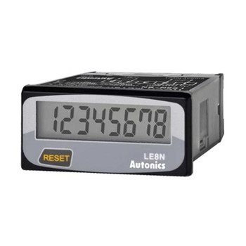
Digital Timer 8 digit, 7 segment LCD, No Voltage Input - LE8N-BN
Autonics