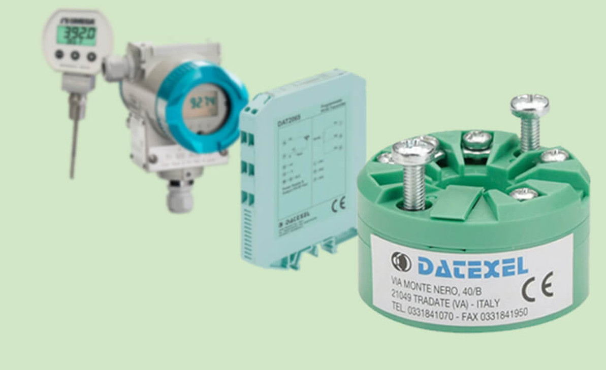
What is a Temperature Transmitter? (Working Principle, Types, Inputs, Outputs and Applications)
A temperature transmitter is an electronic device that is used to convert the signal generated by the temperature sensor such as a thermocouple, RTD, or thermistor to the standard instrumentation signal. This signal indicates the temperature of the process under measurement and control. The most common instrumentation output signal in temperature transmitters is 4 to 20 mA or 0-10V DC ranges. For instance, 4mA can indicate 0°C and 20mA means 100°C. The temperature signal measured by the temperature transmitter is sent to the controller. The action required for the process, such as lowering or raising the temperature, is performed by relevant instrument ordered by the controller.
So transmitters can receive an electronic signal from a temperature sensor and convert it into a reliable signal. This signal is easily transmissible and is provided to the control or processing unit.
Usually, the output signal of the transmitters is sent to a control device, such as PLC, DCS, PC, loop controller, data logger, display, or recorder.
Temperature transmitters come in a variety of shapes and sizes that we will talk about it in the following paragraphs. The Choosing of a temperature transmitter depends on the application and the environment used.
Temperature transmitters act as an interface between the control system and the temperature sensor, which isolate, amplify, linearize and convert the input signal from the sensor and then send a standardized output signal to the control system to be able to provide accurate temperature monitoring with a low degree of interference.
Working principle of a Temperature Transmitter
The temperature transmitter, proportional to the input of the temperature sensor, supplies its current from a DC power supply and ultimately transmits the actual signal as a change in the power supply.
For instance, a thermocouple input transmitter draws a current of 4 mA from the power supply during the lowest temperature measurement.
Then, as the temperature increases, the transmitter draws proportionally more current until it reaches 20 mA, which is the maximum temperature sensed by the sensor.
In other words, 4 and 20 mA corresponding to the lowest and highest temperature of the sensor, respectively.
For example, if the sensor temperature range is 0-100 ℃, a 4mA signal would indicate 0℃. In the same way, 20mA would mean 100℃.
When using RTD, the Wheatstone bridge is used to create a low voltage at the end of it. This signal is amplified to generate a 4-20mA signal.
Sometimes, this analog signal is converted to a digital signal (ADC) to permit for additional functions (like calibration and scaling), then returned to the analog signal.
The conditioning circuitry can be designed for resistance values ranging from 15 to 380ohms or something similar to accommodate a full range of RTD values.
When a temperature transmitter is installed in a system, temperature changes cause the thermocouple voltage or RTD internal resistance to change, with the output current varying between 4 and 20 mA.
These changes lead to the creation of an internal circuit that is converted to temperature data by the converter and eventually sent to the control room.
Transmitters are designed in various types and are marketed for use. One group of transmitters is wireless and the other group is wired. The wired type of these tools is divided into two categories: 2-wire and 4-wires.
2-Wire Temperature Transmitter
Temperature transmitters usually require a power supply and are made in the form of 2 wires. Power supply and signal transmission in these models is done by two wires.
4-Wire Temperature Transmitter
The 4-wire transmitter has two separate circuits. In this model, two wires are employed to connect to the power supply and the other two wires are used to connect to the controller. The power supply can be AC or DC, depending on the manufacturer and model of the device.
Types of temperature transmitters based on shapes and sizes
Temperature transmitters come in a variety of shapes and sizes. The choice of temperature transmitter depends on the application and the environment used.
They are divided into the following categories according to how they are installed:
Panel Mount or DIN Rail Mount Temperature Transmitter
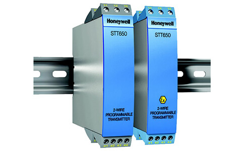
These transmitters are usually used in locations where an electrical box or a surface with a standard rail or DIN rail is necessary. DIN rail is industry-standard mounting hardware for equipment installation.
Some features of this transmitter are:
- There are mounting brackets on the bottom of these transmitters. With these parts, the transmitter can be installed on the DIN rail.
- They have durable housing for installation in industrial environments.
- They are modular in size and the best choice for space-saving.
- DIN Rail transmitters have relatively accurate and precise performance.
- Screw terminals increase installation speed and wiring.
- They are relatively low-cost and can perform with an array of different sensors
Head Mount or Hockey Puck Style Temperature Transmitter
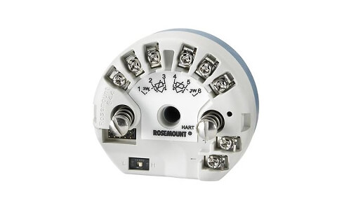
Hockey puck transmitters are one of the most common types of transmitters and are used for basic applications. Its name is derived from its form factor.
The dimensions of this transmitter are small and they offer limited hardware. These low-cost transmitters are also well suited for OEM applications and are suitable to be placed inside the heads of temperature probes.
Also, there are two mounting holes on each side of the transmitter.
Field Mounted Temperature Transmitter

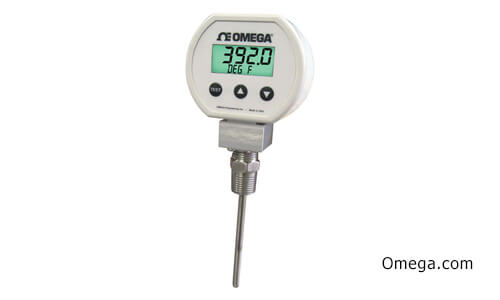
This special type of temperature transmitter is mounted in its own exterior housing. This feature enables it to be used “in the field” where conditions may need extra protection, such as in high-performance industrial operations.
By placing Field mounted transmitters relatively close to the sensor the strength of the signal will increase.
This transmitter is designed to protect sensitive electronic components against various conditions such as humidity, environmental conditions, corrosion and..
Inputs of Temperature Transmitter
Temperature transmitter supports various input signals, such as RTD, thermocouple, resistance and voltage signal.
Thermocouples and RTDs are the most common types of inputs for temperature transmitters.
Thermocouple Input
Nowadays in the industry, thermocouple transmitters are commonly designed for metal-based thermocouples, which include: K ، T ، J و E. you can find transmitters for other types of thermocouples, but they may be more expensive.
Thermocouples have two wires and their transmitter must have two input terminals. The thermocouple wires must be connected to the transmitter inputs.
To use a thermocouple, a transmitter must be provided with cold junction compensation. Zero and Span dialog are also common in thermocouple transmitters. With these dialogs, the device can be calibrated. This feature will be very important when the device is reading incorrect values.
Resistance Temperature Detector (RTD) Input
RTD inputs are designed depending on their resistance value. The resistance is determined by the material used when making the wire-wound.
Platinum is a common material used for this purpose and has a temperature coefficient of 0.00392 //℃. Hence, a wide range of resistance values can be created using it.
Resistance can vary from 10 to 10,000, but the most common type of it is 100, known as the PT100.
Determining the value of RTD is a significant step in specifying the input for the transmitter. The next step is to determine the number of RTD wires.
RTDs There are 3 different wiring configurations for RTD: 2-wire, 3-wire, and 4-wire, each of which requires different circuits.
The 3-wire configuration is the most economical option and offers the best accuracy and precision. Thermistors are well suited when the temperature range is small, but the response should be high.
Outputs of Temperature Transmitter
Temperature transmitters act as intermediaries between the sensor and the receiver. Therefore, they must produce a value that can be measured by the receiver.
The output signal of the transmitter can be one of the standard currents of 4 -20 mA, 0-5 VDC or 0-10VDVD. 4 -20 mA is the most common type of output signal in the industry.
There is no need for an additional power supply at the remote location as the transmitter is powered by a low-level output current of 4 - 20 mA. In addition, the usual signal of 24 Vdc is standard for operations in plants that possess large amounts of precision tools.
The output signal of the transmitter is highly immune when there is ambient electrical noise. Any noise appearing in the output current is usually omitted by rejecting the common mode of the receiving system.
Furthermore, the current output signal, unlike most voltage signals, does not change (decrease) with increasing distance.
Digital Temperature Transmitter
It is a term that has existed and its meaning is evolving. Historically, a digital transmitter was referred to as a smart transmitter.
The SMART transmitter is an intelligent transmitter with analog output of 4 to 20 mA. Also, these transmitters provide other information digital communication signal data including instrument Tag Names, Calibration Data, and Sensor Diagnostics.
HART protocol or FOUNDATION FIELDBUS or PROFIBUS are usually used to set up smart transmitters.
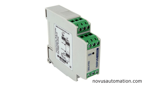
Isolated Temperature Transmitter
Before explaining the Isolated Temperature Transmitter it is important to know what a ground loop is.
If a grounding rod is connected to the ground at two different points and a voltmeter is connected between them, the voltage difference is detected between the two.
This potential difference actually exists between the two points on the earth's surface. When we want to measure a process at a remote location, this voltage difference causes an error current along the line, which is called the "ground loop" signal. The result will be shown as an error on the display.
So, to avoid "ground loop" errors, you should choose an isolating temperature transmitter for your device.
This type of transmitter in the form of optoelectronic isolates the sensor signal from the output current loop.
In this way, the user can ground both the sensor and one side of the current loop. isolated transmitters support electrical devices by removing the effects of the ground loop, reducing undesirable interferences and instabilities in sensor measurements.
Temperature transmitter calibration
Adjustment and calibration are used to increase the accuracy of the transmitter output and to match the specific sensor.
Output signal changes should adequately reflect temperature changes. Like any instrumentation transmitter, a temperature transmitter should be calibrated or adjusted so that the current output of 4 to 20 mA indicates the varying temperature range of the measured process variable.
For instance, a temperature transmitter with a temperature range of 0°C to 400°C generates an output current of 4 to 20 mA.
Devices that can simulate the output of sensors can be used to calibrate transmitters. For example, instead of a thermocouple sensor, a device that generates a range of millivolts can be used.
To calibrate the RTD sensor, a device that produces a range of resistances called a decade box is used.
Old-style temperature transmitter calibration
Older temperature transmitters provide multi-turn potentiometer adjustments called Zero and Span. The zero potentiometers generate a current of 4 mA when simulating a temperature of 0%.
Span potentiometer is also used to generate a 20 mA current when simulating 100% temperature.
New style temperature transmitter calibration
Newer transmitters do not offer Span and Zero adjustments and calibration is done through software. In this case, a USB cable is usually needed to connect the transmitter to the computer.
The smart temperature transmitter for configuration freely uses the DIP switch or PC. the type of input signal, the range of measurement, and cold junction compensation of the thermocouple, optional HART communication function are automatically adjusted by the transmitter with high accuracy, long operating lifespan, low-temperature drift, and easy replacement.
Smart temperature transmitters are rapidly configured for a specific application. They allow the configuration through PAD or standard PC using the software. We can configure input parameters, output, sensor error detection, and process calibration in a few minutes.
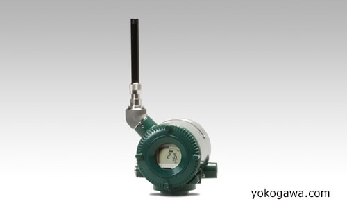
Wireless Temperature Transmitter
Wireless transmitters are the latest models. In these devices, a Wi-Fi signal is used to transmit the signal to the receiver or controllers. After receiving the signal, it can be sent to a computer in order to be stored and printed or exported later on a spreadsheet. Also, the received signal can be sent through the wire as a 4 - 20 mA signal to a PLC.
Why should we use a temperature transmitter?
In many industrial cases, the temperature of a process must be controlled remotely. Signals generated by temperature sensors, such as thermocouples, are very weak signals and cannot be sent over long distances.
These sensors can be connected to a transmitter to amplify small signals and reach the desired value of the control system. When the signals become transferable, they can be transmitted to control equipment and controllers.
Advantages of using temperature transmitters
Using this tool has numerous advantages over using its direct-wired counterparts, which include:
- Electrical noise and signal degradation are greatly reduced by the use of transmitters.
- The cost of using an expensive extension wire by using a transmitter is significantly reduced.
- Temperature transmitters have the ability to involve local indication and control and provide advanced diagnostics.
In which industries is a temperature transmitter used?
Temperature transmitters are widely used in large industries where temperature sensors are used including:
- Aerospace
- Chemical
- Food and beverage
- Energy
- air conditioning
- Metal plating
- mining
- Oil and Gas
- Petrochemical
- Waste and water management
Recent Posts
-
Booster Pump Troubleshooting and Maintenance: How to Fix and Prevent Common Issues
1. Introduction Imagine turning on your faucet only to be greeted with a weak trickle of water when …22nd Apr 2025 -
Energy-Efficient Booster Pumps: Selection and Tips for Maximizing Performance
1. Introduction Imagine never having to deal with fluctuating water pressure, noisy pumps, or skyroc …19th Apr 2025 -
Booster Pumps for Sustainable Water Systems: Irrigation and Rainwater Harvesting Solutions
1. Introduction Water scarcity is no longer a distant threat—it’s a reality affecting millions …16th Apr 2025

