

Flow Meter Outputs
There are numerous types of flow meter output which are discussed below.
1-reed switch

Reed switch is the simplest type of pulse output. It is a magnetically operated switch in a glass capsule.
Typically Reed switches are cheaper and simpler to understand but restrained to lower frequencies.
They may be utilized in dangerous areas. The tool only changes the voltage provided to it and if the voltage is protected properly the reed switch functions perfectly.
The logging flow meter “sees” the voltage switching whilst it closes.
Reed Switches, however, have some disadvantages. They are mechanical switches and feature a limited lifetime since exhaustion and failure are probable after almost 109 operations under the best circumstances.
The contacts must be preserved by a current limiting component to avoid a supply being straightly switched, inflicting them to weld together.
In dangerous areas this greater safety can stop an intrinsically secure device reading the contact closures.
Furthermore, there is also a potential challenge with contact bounce which imposes very excessive frequency pulses which may be visible by a lot of modern electronic tools.
2-Transistors
They are simple solid-state switches that can be commonly configured in Open Collectors, this means you need to add a few external circuitry, like a resistive load configured for PNP or NPN.
1. NPN. An Open Collector NPN output is configured like a switch to the 0 V supply of the flow meter.
It needs a ‘Pull-Up’ resistor to a positive voltage. The advantage here is that this voltage may not necessarily be the supply voltage of the sensor as indicated below but can be any selected (inside detailed limits) to suit the remaining instrumentation network for example 24 volts for more secure transmission over longer distances.

2. PNP. An Open Collector PNP output is the mirror configuration of the NPN counterpart, providing a switch to the sensor supply voltage.
Although more popular with many PLCs; in practice, the PNP output is much less flexible than that of the NPN. Typical pull-down resistor values are also between 1K and 50kOhm.

3- Logic output
A logic output is an output that switches (conditions described as logic 1 and logic 0) between predetermined voltage levels.
The most common logic output tools are CMOS and TTL. TTL is described as a logic 0 (output below 0.4V) and a logic 1 (above 2.4V).
Usually, a 0 is a few mV and a 1 is close to 5V. CMOS is described relative to an internal supply voltage (usually 3.3V or 5V) as having a 0 at below 33% of the supply voltage and a 1 at above 66%.
In practice, CMOS output might have a 0 output at virtually 0V and a 1 output near the internal supply.

4-Namur Sensor (EN 60947-5-6)
It is a two-wire sensor that is provided with a constant voltage. With a Namur sensor, as the flow though the flowmeter varies the resistance of the sensor changes.
In most cases, the current cycles from 2.1 to 1.2 mA as the target passes the sensor.
These instruments with Namur output are generally used with flow meters expert in unsafe regions because the energy intake is very low and the change in resistance or current could be monitored remotely. Converters to standard outputs are accessible.
5-Magnetic coil
If you move a magnet in the front of a coil, you get a voltage. Implemented in a flow meter the magnet and the coil are stationary in the sensor and a magnetic turbine blade alters the magnetic coupling enough to result in a voltage swing.
Though brought about voltages are usually low levels (c.10 millivolts) they are cyclical and pretty simple to figure out. If the surroundings wherein the sensor works are electrically “noisy” the signal has to be amplified or transformed to an improved degree previous to transmission. As shown above, in the NPN section low voltage pulses do not travel properly over long distances.

The table below offers a beneficial summary to help you select the most optimal flowmeter.

Calculate Flow Transmitter Output Current
A flow transmitter is ranged from 0 to 350 GPM, 4-20 mA output, direct-responding. Calculate the current signal value at a flow rate of 204 GPM.
This problem can be solved using standard 4-20mA conversion Formula.
One way we can resolve the amount of signal current is to convert the flow value to 204.

GPM into a ratio of the flowmeter’s full-flow value, then apply the same formula we used in the preceding instance referring to percentage to milliamps.
Converting the flow rate into a “per unit” ratio is a matter of simple division because the flow measurement variety is zero-based:
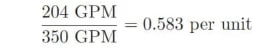
Converting a "per unit" ratio into percent merely requires multiplication by 100, since *percent" literally means "per 100":

Next, we plug this percentage value into the formula:
Flow Transmitter Calculations:
An alternative approach is to set up a linear equation mainly for this flow meter, given its measurement variety (0 to 350 GPM) and output signal range (4 to 20 mA). We will start this process by sketching a simple graph referring to flow rate to the current:
![]()
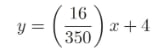
The slope (m) for this equation is rise over run, in this case 16 milliamps of rise for 350 GPM of run:
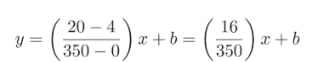
The y-intercept for this equation is 4, since the current output will be 4 milliamps at zero flow:
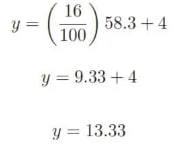
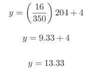
Now that the linear equation is set up for this particular flow meter, we may plug in the 204 GPM value for i and solve for current:
Tap here to get more information about Flow Meters:
Flow meter (Working Principle, Different Types and FAQs)
Flow Meter Vs. Flow Transmitter Vs. Flow Switch
Flow Rate (Volume Flow Rate, Mass Flow Rate)
Recent Posts
-

Booster Pump Troubleshooting and Maintenance: How to Fix and Prevent Common Issues
1. Introduction Imagine turning on your faucet only to be greeted with a weak trickle of water when …22nd Apr 2025 -

Energy-Efficient Booster Pumps: Selection and Tips for Maximizing Performance
1. Introduction Imagine never having to deal with fluctuating water pressure, noisy pumps, or skyroc …19th Apr 2025 -

Booster Pumps for Sustainable Water Systems: Irrigation and Rainwater Harvesting Solutions
1. Introduction Water scarcity is no longer a distant threat—it’s a reality affecting millions …16th Apr 2025