

Bridging Light and Pressure: The Futuristic Realm of Optical Pressure Sensor
In the realm of modern sensing technology, optical pressure sensors stand as a remarkable innovation that combines the precision of optics with the practicality of pressure measurement. These sensors harness the principles of light propagation and its interaction with pressure-induced deformations to deliver accurate and reliable pressure readings across a multitude of applications. By translating pressure changes into optical signals, optical pressure sensors have found their way into industries as diverse as aerospace, medical, industrial automation, and environmental monitoring.
In this age of ever-advancing technology, understanding the intricacies of optical pressure sensors is vital. This conversation will delve into the working principles, types, advantages, disadvantages, applications, calibration, and considerations that define the landscape of optical pressure sensing. Whether you're seeking to grasp the core concepts or aiming to make an informed choice for your specific needs, this exploration will illuminate the path toward effectively utilizing these innovative devices.
From their role in aircraft cabin pressure regulation to monitoring critical components in industrial processes, optical pressure sensors have earned a place at the forefront of pressure measurement technology. By the end of this comprehensive discussion, you'll be equipped with the knowledge necessary to appreciate their significance, make informed decisions, and potentially contribute to the development of novel applications for these cutting-edge sensors.
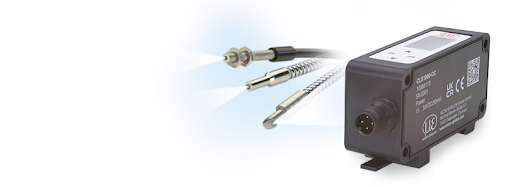
Fig 1. Optical pressure sensor
What is an Optical Sensor?
An optical sensor is a device that uses light to detect and measure various physical properties, such as light intensity, color, position, motion, or distance. It converts changes in light into electrical signals that can be interpreted by electronic circuits or computers. Optical sensors are widely used in a variety of applications, ranging from simple devices like ambient light sensors in smartphones to more complex systems in industrial automation, medical devices, robotics, and more.
There are different types of optical sensors, each designed for specific purposes:
- Photoelectric Sensors: These sensors use light beams to detect the presence, absence, or movement of objects. They are commonly used in industrial automation for tasks like object counting, position detection, and packaging.
- Proximity Sensors: These sensors detect the presence or absence of an object without any physical contact. They can work by measuring the reflection or interruption of light beams.
- Color Sensors: Color sensors can determine the color of an object by analyzing the light it reflects. They are used in applications like color sorting, quality control, and image processing.
- Ambient Light Sensors: These sensors measure the intensity of ambient light and are often used in displays and automatic lighting systems to adjust brightness based on the surrounding light conditions.
- Distance and Position Sensors: These sensors determine the distance between the sensor and an object by measuring the time it takes for light to travel to the object and back. This principle is used in technologies like LiDAR (Light Detection and Ranging).
- Fiber Optic Sensors: Fiber optic sensors use optical fibers to transmit and receive light signals. They can be used for various purposes, such as measuring temperature, pressure, and strain in harsh environments.
- Photodiodes and Phototransistors: These are basic light-sensitive devices that convert light energy into electrical current. They are used in applications like light meters, communication systems, and optical communication (fiber optics).
- Image Sensors: Image sensors capture visual information and convert it into electrical signals, commonly used in digital cameras, smartphones, and surveillance systems.
Optical sensors offer advantages such as high sensitivity, fast response times, non-contact operation, and resistance to electrical interference. Their versatility and accuracy make them essential components in many modern technologies.
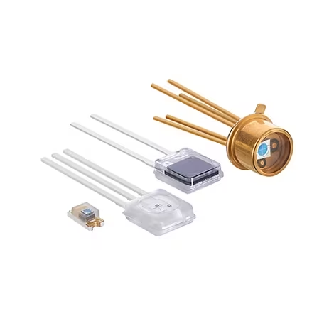
Fig 2. Optical sensors
Optical Pressure Sensor are essential tools for many industrial applications, but for a wider range and more advanced features, check our Pressure Sensor Products.
What is an Optical Pressure Sensor?
An optical pressure sensor, also known as an optical pressure transducer, is a type of sensor that uses optical principles to measure pressure. Instead of relying on traditional mechanical or electrical methods to sense pressure changes, these sensors utilize optical properties to translate pressure-induced changes into measurable optical signals. This approach often provides advantages in terms of accuracy, sensitivity, and resistance to harsh environments.
The basic working principle of an optical pressure sensor involves the interaction between light and a sensing element that responds to pressure variations. Here's a simplified overview of how it works:
- Sensing Mechanism: The sensor contains a material or structure that undergoes changes in optical properties when subjected to pressure. This could involve changes in refractive index, absorption, or scattering of light.
- Optical Interrogation: A light source, typically a laser or LED, emits light towards the sensing element. The optical properties of the sensing element change in response to pressure variations. These changes cause alterations in the way the light interacts with the material.
- Optical Signal Modulation: The altered light interactions lead to changes in the optical signal. This modulation can be in the form of intensity, wavelength, phase, or polarization changes.
- Detection: A photodetector or sensor array captures the modified optical signal. This detection process quantifies the changes in the optical properties of the sensing element.
- Signal Processing: The captured optical signal is processed using electronics or computational methods to extract pressure-related information. Calibration may be necessary to convert the optical signal changes into pressure measurements.
The advantages of optical pressure sensors include high accuracy, minimal drift over time, immunity to electromagnetic interference, and the ability to be used in challenging environments like high-pressure or corrosive conditions. Additionally, some optical pressure sensors can be designed for distributed sensing, where pressure variations can be monitored along the length of an optical fiber.
Applications of optical pressure sensors are diverse and span various industries:
- Aerospace and Aviation: Monitoring cabin pressure, fuel pressure, and other critical parameters in aircraft.
- Medical Devices: Monitoring blood pressure, intracranial pressure, and fluid pressure in medical equipment.
- Industrial Processes: Measuring pressure in pipelines, vessels, and chemical processes.
- Automotive: Monitoring tire pressure, engine combustion pressures, and brake systems.
- Oil and Gas: Monitoring pressure in oil wells, pipelines, and drilling operations.
It's worth noting that there are different designs and technologies within the realm of optical pressure sensors, and specific implementations can vary. Some sensors directly measure pressure-induced changes in the optical properties of materials, while others might utilize interferometric techniques, fiber Bragg gratings, or other advanced methods to achieve the desired pressure-sensing capabilities.
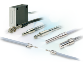
Fig 3. Optical pressure sensors
History of Optical Pressure Sensor
The history of optical pressure sensors can be traced back to the mid-20th century, with developments in optics, materials science, and electronics paving the way for their creation. Here is an overview of the key milestones in the evolution of optical pressure sensor technology:
- 1960s - Early Concepts: The groundwork for optical pressure sensing was laid in the 1960s. Researchers explored the use of optical fibers as sensors for various parameters, including pressure. However, the technology was in its infancy, and practical implementations were limited by the available materials and techniques.
- 1970s - Fiber Optic Sensors: The concept of using optical fibers for sensing gained traction in the 1970s. Researchers began experimenting with fiber Bragg gratings, which are periodic variations in the refractive index of an optical fiber. These gratings could be affected by pressure changes, leading to a change in the transmitted light's characteristics.
- 1980s - Interferometric Sensors: In the 1980s, interferometric pressure sensors started to emerge. Michelson and Fabry-Perot interferometers were adapted for pressure-sensing applications. These interferometric sensors relied on changes in the length of an optical cavity due to pressure variations.
- 1990s - Miniaturization and Applications: The 1990s marked a period of advancement in microfabrication and optoelectronics. This allowed for the development of miniaturized and more practical optical pressure sensors. Researchers and engineers explored various designs, materials, and configurations to improve accuracy and sensitivity.
- 2000s - Diverse Applications: As optical technology continued to advance, optical pressure sensors found applications in industries such as aerospace, medical devices, and oil and gas. Innovations in materials, signal processing, and multiplexing techniques further expanded the capabilities and reliability of these sensors.
- The 2010s - Distributed Sensing and Advances: The 2010s saw significant developments in distributed optical sensing systems. Researchers began using techniques like Rayleigh scattering in optical fibers to create distributed pressure sensors that could monitor pressure variations along the length of the fiber.
- Recent Advances: In recent years, advances in nanotechnology, photonic materials, and integrated optics have continued to enhance the performance of optical pressure sensors. These sensors are now more rugged, accurate, and capable of withstanding challenging environmental conditions.
Throughout this history, optical pressure sensors have benefited from the broader advancements in optics, materials science, and electronics. The rise of optoelectronics and the integration of photonic components into sensor systems have also contributed to their evolution.
It's important to note that the development of optical pressure sensors is ongoing, with researchers and engineers continuously working to improve their performance, versatility, and applications across various industries. As new technologies emerge and our understanding of light-material interactions deepens, the field of optical pressure sensing is likely to continue evolving.
Optical Pressure Sensor Structure
The structure of an optical pressure sensor can vary depending on the specific design and technology used. However, the basic components and principles remain relatively consistent. Here's a generalized structure of an optical pressure sensor:
- Sensing Element: The sensing element is the heart of the optical pressure sensor. It's part of the sensor that directly interacts with the pressure changes and exhibits corresponding changes in optical properties. The choice of material and design for the sensing element depends on the specific application and the desired sensitivity.
- Optical Source: An optical source, such as a laser diode or LED, emits light that interacts with the sensing element. The light emitted can have specific wavelengths, intensities, or modulation characteristics, depending on the sensor's design.
- Optical Pathway: The emitted light travels through an optical pathway, which might include lenses, mirrors, and fiber optics. This pathway ensures that the light reaches the sensing element and collects the modified light after it interacts with the sensing element.
- Sensing Mechanism: The sensing mechanism is the core element where pressure-induced changes in optical properties occur. This could involve changes in refractive index, absorption, or scattering of light. For example, in fiber Bragg grating sensors, pressure-induced deformations cause shifts in the Bragg wavelength, which in turn affect the reflected light.
- Optical Modulation: The changes in the optical properties of the sensing element lead to modulation of the optical signal. This modulation could manifest as changes in light intensity, wavelength, phase, or polarization.
- Photodetector: A photodetector or sensor array captures the modified optical signal that has interacted with the sensing element. The photodetector converts the optical signal into an electrical signal that can be processed and analyzed.
- Signal Processing: The captured electrical signal is processed using electronics or computational methods. This processing can involve amplification, filtering, demodulation, and data analysis to extract the pressure-related information from the optical signal.
- Output and Display: The processed pressure information can be presented through various means, such as digital displays, analog outputs, or communication interfaces. This allows users or systems to monitor the pressure changes in real-time.
- Calibration: Optical pressure sensors typically require calibration to establish a relationship between the changes in the optical signal and actual pressure values. This involves testing the sensor under known pressure conditions and creating a calibration curve or equation.
- Housing and Protection: The entire sensor assembly is often enclosed in a protective housing to shield it from environmental factors like moisture, temperature fluctuations, and mechanical impacts. The housing also ensures that the sensor maintains accuracy and reliability over time.
It's important to note that there are various types of optical pressure sensors, each with its unique design and sensing principles. Some sensors might use interferometric techniques, while others rely on changes in the refractive index of materials. The specific components and arrangement can differ, but the underlying concept of using optical properties to measure pressure remains consistent.
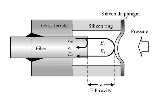
Fig 4. Structure of optical pressure sensor
Optical Pressure Sensor working principle
The working principle of an optical pressure sensor involves utilizing changes in the optical properties of a sensing element due to pressure variations. These changes are then converted into measurable optical signals, which are subsequently processed to determine the pressure value. Here's a step-by-step explanation of how an optical pressure sensor typically works:
- Sensing Element Preparation: The optical pressure sensor includes a sensing element designed to undergo changes in optical properties when subjected to pressure changes. This element can be a specially designed material or structure that responds to pressure-induced deformations.
- Optical Source Emission: An optical source, often a laser diode or LED, emits light of a specific wavelength. This light is directed towards the sensing element.
- Interaction with Sensing Element: As pressure changes, the sensing element deforms or undergoes some physical changes. These changes alter the optical properties of the element, such as its refractive index, absorption, or scattering characteristics.
- Modulation of Optical Signal: The altered optical properties of the sensing element lead to a modulation of the emitted light. This modulation can manifest as changes in light intensity, wavelength, phase, or polarization.
- Capturing the Modulated Light: The modulated light, which has interacted with the sensing element, is collected and directed toward a photodetector. The photodetector converts the optical signal into an electrical signal.
- Electrical Signal Processing: The electrical signal from the photodetector is then processed using electronics and signal processing techniques. This processing might involve amplification, filtering, and demodulation to extract the pressure-related information from the electrical signal.
- Calibration and Conversion: Optical pressure sensors typically require calibration to establish a relationship between the changes in the optical signal and actual pressure values. This calibration process involves testing the sensor under known pressure conditions and creating a calibration curve or equation.
- Pressure Determination: Using the calibrated relationship, the processed electrical signal is converted into pressure values. This information represents the pressure applied to the sensing element.
- Output and Display: The pressure value can be presented to users or systems through various means, such as digital displays, analog outputs, or communication interfaces. This allows real-time monitoring and analysis of pressure variations.
- Environmental Factors: To ensure accuracy and reliability, the entire sensor assembly is often enclosed in a protective housing that shields it from environmental factors like temperature changes, moisture, and mechanical impacts.
The specific working principle can vary based on the type of optical pressure sensor. For example, fiber Bragg grating sensors rely on changes in the Bragg wavelength due to pressure-induced deformations in the optical fiber, while Fabry-Perot interferometric sensors use changes in the length of an optical cavity. Other types of optical pressure sensors may utilize different optical phenomena to achieve pressure measurement.
In all cases, the core concept involves converting pressure-induced changes in the optical properties of a sensing element into measurable optical signals, which are then processed and converted into pressure values.
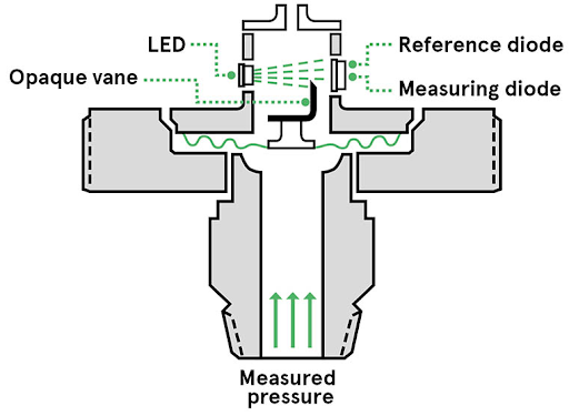
Fig 5. A simple optical pressure sensor
Does an Optical Pressure Sensor have formulas?
Yes, optical pressure sensors often involve mathematical formulas to relate the changes in optical properties to the applied pressure. These formulas are derived from the principles of optics, materials science, and the specific design of the sensor. The exact formulas can vary based on the type of optical pressure sensor and the underlying physical phenomena being exploited. Here are a few examples of optical pressure sensors and the formulas associated with them:
- Fiber Bragg Grating (FBG) Sensor: In FBG sensors, pressure-induced changes in the Bragg wavelength are used to measure pressure. The Bragg wavelength (λ_B) is related to the effective refractive index (n_eff) of the fiber and the grating period (Λ) as follows:
λ_B = 2 * n_eff * Λ
The change in pressure (ΔP) causes a change in the Bragg wavelength, which is related to the strain (ε) in the fiber:
Δλ_B = S * ε = S * ΔL / L
Where S is the sensitivity of the FBG to strain, ΔL is the change in length due to pressure, and L is the initial length of the FBG.
- Fabry-Perot Interferometric Sensor: Fabry-Perot sensors use the interference pattern of light to measure pressure-induced changes in the length of an optical cavity. The change in cavity length (ΔL) is related to the change in wavelength (Δλ) using the formula:
ΔL = Δλ * λ / (2 * n)
Where λ is the wavelength of light used, and n is the refractive index of the medium inside the cavity.
- Microbend Fiber Sensor: Microbend sensors use changes in light intensity due to the bending of optical fibers. The bending-induced strain (ε) is related to the change in light intensity (ΔI) using a formula like
ΔI / I = κ * ε
Where κ is a constant related to the sensitivity of the sensor.
- Distributed Fiber Optic Sensors: In distributed sensing, such as using Rayleigh scattering in optical fibers, the pressure-induced strain can be related to changes in scattering intensity. The relationship can be complex and might involve integrating changes along the length of the fiber.
These are just simplified examples, and actual sensor designs can involve more complex equations, calibration curves, and signal-processing techniques. The specific formulas depend on the sensor's design, the physical principles being utilized, and the calibration process to relate the measured optical signals to pressure values.
Example of using formulas
let's consider an example of a Fiber Bragg Grating (FBG) sensor to demonstrate the use of formulas in an optical pressure sensor.
Example: Fiber Bragg Grating (FBG) Sensor
Suppose we have an FBG pressure sensor with the following parameters:
- Bragg wavelength (λ_B): 1550 nm
- Grating period (Λ): 530 nm
- Sensitivity to strain (S): 1.2 pm/µε (picometers per microstrain)
- Initial length of the FBG (L): 10 mm
We want to calculate the change in pressure (ΔP) that corresponds to a change in Bragg wavelength (Δλ_B) of 5 pm due to pressure-induced strain.
First, we can use the formula for the Bragg wavelength in terms of the effective refractive index (n_eff) and the grating period (Λ):
λ_B = 2 * n_eff * Λ
Since we have the Bragg wavelength and the grating period, we can rearrange this formula to solve for n_eff:
n_eff = λ_B / (2 * Λ)
Substituting the given values: n_eff = 1550 nm / (2 * 530 nm) ≈ 1.46
Next, we can use the sensitivity formula to relate the change in Bragg wavelength (Δλ_B) to the strain (ε):
Δλ_B = S * ε
Solving for strain: ε = Δλ B / S = 5 pm / 1.2 pm/µε ≈ 4.17 µε
Now, let's relate the strain to the change in length (ΔL) of the FBG using the formula for strain: ε = ΔL / L
Solving for ΔL: ΔL = ε * L = 4.17 µε * 10 mm = 41.7 µm
Finally, let's relate the change in length to the change in pressure using appropriate constants and formulas for the specific application. Suppose the sensor has been calibrated, and it's determined that a change of 1 µm in length corresponds to a change of 1 kPa in pressure.
ΔP = ΔL * (1 kPa / 1 µm) = 41.7 kPa
So, in this example, a change in Bragg wavelength of 5 pm corresponds to a change in pressure of approximately 41.7 kPa.
Keep in mind that this is a simplified example for illustrative purposes. In practice, there might be additional factors to consider, such as temperature effects, non-linearities, and calibration procedures.
Formulas table
Certainly, here's a summary table of formulas commonly used in optical pressure sensors, along with a brief description of each formula's purpose and variables:
| Formula | Description | Variables and Constants |
| λ_B = 2 * n_eff * Λ | Relates Bragg wavelength to refractive index and grating period | λ_B: Bragg wavelength, n_eff: Effective refractive index, Λ: Grating period |
| n_eff = λ_B / (2 * Λ) | Calculates effective refractive index | λ_B: Bragg wavelength, Λ: Grating period |
| Δλ_B = S * ε | Relates change in Bragg wavelength to strain | Δλ_B: Change in Bragg wavelength, S: Sensitivity to strain, ε: Strain |
| ε = Δλ_B / S | Calculates strain from change in Bragg wavelength | ε: Strain, Δλ_B: Change in Bragg wavelength, S: Sensitivity to strain |
| ΔL = ε * L | Relates change in length to strain | ΔL: Change in length, ε: Strain, L: Initial length |
| ΔP = ΔL * (1 kPa / 1 µm) | Converts change in length to change in pressure | ΔP: Change in pressure, ΔL: Change in length |
Please note that these formulas are based on simplified principles and assumptions and may require more comprehensive treatment and considerations for real-world applications. Additionally, specific sensor designs and technologies might involve variations in these formulas or require more complex equations to accurately model their behavior.
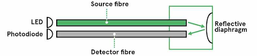
Fig 6. A simple optical pressure sensor
Optical Pressure Sensor Types
Optical pressure sensors come in various types, each utilizing different principles and technologies to measure pressure. Here are some common types of optical pressure sensors:
- Fiber Bragg Grating (FBG) Sensor: FBG sensors use periodic variations in the refractive index along an optical fiber to create a grating. Pressure-induced changes in the fiber's length or strain cause shifts in the Bragg wavelength, allowing measurement of pressure changes.
- Fabry-Perot Interferometric Sensor: Fabry-Perot sensors use an optical cavity formed between two reflective surfaces. Pressure-induced changes in the cavity length cause shifts in the interference pattern, which are detected as changes in optical intensity or wavelength.
- Microbend Fiber Sensor: Microbend sensors rely on changes in light intensity due to bending-induced changes in the fiber's refractive index. Pressure-induced mechanical deformations cause microbends, altering the light propagation characteristics.
- Distributed Fiber Optic Sensors: These sensors use variations in light scattering along an optical fiber to detect pressure changes. Rayleigh scattering, Brillouin scattering, and Raman scattering are commonly utilized principles for distributed pressure sensing.
- Optical MEMS Sensors: Micro-Electro-Mechanical Systems (MEMS) devices integrate microstructures with optical elements. MEMS pressure sensors can modulate light intensity, wavelength, or phase based on mechanical deformations caused by pressure.
- Microfluidic Sensors: Microfluidic sensors combine microfluidic channels with optical elements to measure pressure changes in fluid systems. Pressure-induced deformations affect light propagation through the microfluidic structures.
- Photonic Crystal Pressure Sensor: Photonic crystal sensors use periodic structures to create bandgaps that are sensitive to changes in refractive index. Pressure-induced changes in the surrounding medium affect the photonic bandgap, leading to measurable shifts in wavelength or intensity.
- Optoacoustic Sensors: Optoacoustic sensors generate acoustic waves in response to pressure changes, which are detected optically. Laser-induced heating of a material causes thermal expansion and generates acoustic waves that can be detected with optical techniques.
- Birefringence-based Sensors: Birefringence sensors measure pressure-induced changes in the birefringence of a material. Changes in stress or strain alter the polarization properties of light passing through the material.
- Optical Pressure Transducers: These transducers often use diaphragms that deform under pressure to modulate light intensity or wavelength. Changes in diaphragm shape cause changes in the optical signal, which are then correlated with pressure.
Each type of optical pressure sensor has its own advantages, limitations, and suitable applications. The choice of the sensor depends on factors such as required accuracy, sensitivity, environmental conditions, and intended application domain.
- Working Principle: FBG sensors use periodic variations in the refractive index of an optical fiber. When subjected to pressure-induced strains, the grating period changes, leading to shifts in the Bragg wavelength.
- Applications: Aerospace (aircraft cabin pressure, structural health monitoring), oil and gas (wellbore pressure), civil engineering (bridges, pipelines), medical devices (intracranial pressure), and more.
- Advantages: High sensitivity, accuracy, immunity to electromagnetic interference, and compatibility with optical fiber networks.
- Disadvantages: Requires precise calibration, temperature effects can influence measurements, and sensitivity may decrease with longer fibers.
Fiber Bragg Grating (FBG) Sensor:
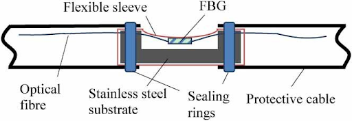
Fig 7. FBG pressure sensor
- Working Principle: Fabry-Perot sensors use an optical cavity between reflective surfaces. Pressure-induced changes in the cavity length cause shifts in the interference pattern, detected as changes in optical intensity or wavelength.
- Applications: Aerospace (aerodynamic pressure), industrial processes (fluid pressure), biomedical (blood pressure monitoring), and geophysical research.
- Advantages: High sensitivity, wide pressure range, and resistance to electromagnetic interference.
- Disadvantages: Requires precision alignment, susceptible to temperature effects, and can be sensitive to alignment changes.
Fabry-Perot Interferometric Sensor:
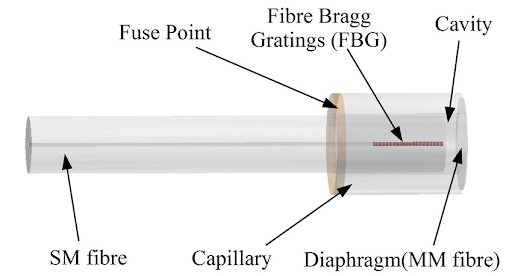
Fig 8. Schematic of the Extrinsic Fabry Perot Interferometer
- Working Principle: Microbend sensors rely on changes in light intensity due to mechanical deformations in the fiber caused by bending. Pressure-induced mechanical deformations lead to microbends, altering the light propagation characteristics.
- Applications: Fluid pressure monitoring, industrial automation, robotics, and biomedical applications.
- Advantages: Simple design, cost-effective, and can be integrated into small spaces.
- Disadvantages: Limited sensitivity, susceptibility to environmental factors like temperature and vibration, and potential for hysteresis.
Microbend Fiber Sensor:
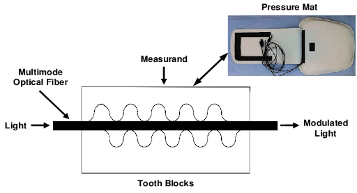
Fig 9. Basic microbend fiber optic sensor
- Working Principle: Distributed sensors use variations in light scattering along an optical fiber to detect pressure changes. Pressure-induced deformations cause changes in light scattering patterns.
- Applications: Oil and gas (pipeline monitoring), structural health monitoring (bridges, dams), geophysical monitoring, and environmental monitoring.
- Advantages: Long sensing range, can cover large areas, immune to electromagnetic interference, and suitable for harsh environments.
- Disadvantages: Lower spatial resolution compared to point sensors, complex signal processing required for data interpretation.
Distributed Fiber Optic Sensors:
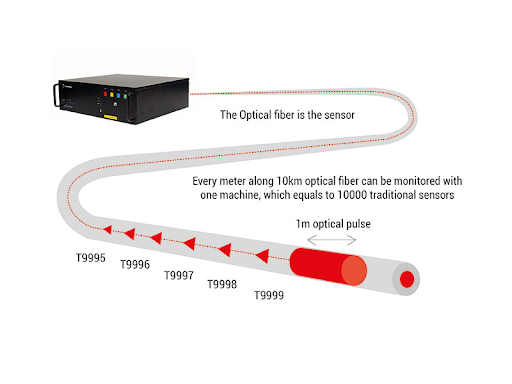
Fig 10. Distributed Fiber Optic Sensor
- Working Principle: MEMS sensors combine microstructures with optical elements. Pressure-induced mechanical deformations alter light propagation characteristics, leading to changes in optical signals.
- Applications: Consumer electronics (smartphones, wearables), medical devices (blood pressure monitoring), and automotive applications.
- Advantages: Miniaturization, integration with electronics, high sensitivity, and potential for multiplexing.
- Disadvantages: Sensitivity to mechanical wear, limited to specific pressure ranges, and potential for reliability issues.
Optical MEMS Sensors:
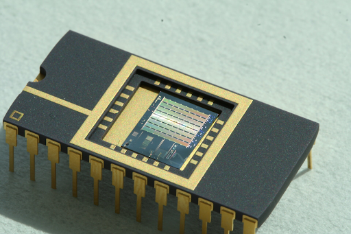
Fig 11. Optical MEMS Sensors
- Working Principle: Microfluidic sensors combine microfluidic channels with optical elements. Pressure-induced deformations in microfluidic channels affect light propagation, leading to changes in optical signals.
- Applications: Biomedical research (cellular studies, drug screening), chemical analysis, and lab-on-a-chip systems.
- Advantages: Precise control of fluid environments, potential for high throughput, and compatibility with lab-scale experiments.
- Disadvantages: Limited pressure range, susceptibility to fluid flow variations, and challenges in fabrication and integration.
Microfluidic Sensors:
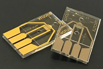
Fig 12. Microfluidic Sensor
- Working Principle: Photonic crystal sensors utilize photonic bandgaps sensitive to changes in refractive index caused by pressure. Pressure-induced changes in the surrounding medium alter the photonic bandgap, leading to shifts in wavelength or intensity.
- Applications: Environmental monitoring, biomedicine, and chemical sensing.
- Advantages: High sensitivity, label-free detection, and potential for integration with microfluidic systems.
- Disadvantages: Complex fabrication, limited pressure range, and susceptibility to environmental factors.
- Working Principle: Optoacoustic sensors generate acoustic waves due to pressure-induced thermal expansion. These acoustic waves are detected optically.
- Applications: Biomedical imaging (photoacoustic imaging), gas analysis, and industrial leak detection.
- Advantages: High resolution, non-invasive imaging, and potential for imaging deep tissues.
- Disadvantages: Complex setup, limited pressure range, and sensitivity to acoustic attenuation.
- Working Principle: Birefringence sensors measure pressure-induced changes in birefringence, which alter the polarization properties of light passing through the material.
- Applications: Aerospace (structural monitoring), geophysical research, and material characterization.
- Advantages: Directly measures stress-induced birefringence, potential for distributed sensing.
- Disadvantages: Limited pressure range, sensitivity to temperature and mechanical factors, and complex signal processing.
Photonic Crystal Pressure Sensor:
Optoacoustic Sensors:
Birefringence-based Sensors:
Each type of optical pressure sensor has its own strengths and weaknesses, making them suitable for different applications and environments. The choice of sensor depends on factors such as required accuracy, pressure range, sensitivity, robustness, and specific application requirements.
Comparing table
Here's a comparison table that summarizes the key features of different types of optical pressure sensors:
| Sensor Type | Working Principle | Applications | Advantages | Disadvantages |
| Fiber Bragg Grating (FBG) | Measures Bragg wavelength shift due to strain | Aerospace, oil and gas, medical, structural health | High sensitivity, immunity to EMI, accuracy | Requires calibration, temperature effects |
| Fabry-Perot Interferometric | Monitors interference pattern shifts in cavity | Aerospace, industrial, biomedical, geophysics | High sensitivity, wide range, EMI resistance | Alignment sensitivity, temperature effects |
| Microbend Fiber | Detects light intensity changes due to bending | Fluid pressure, industrial, biomedical | Simple design, cost-effective | Limited sensitivity, environmental effects |
| Distributed Fiber Optic | Uses scattering changes along fiber to measure | Structural health, oil and gas, environmental | Long range, immune to EMI, harsh env. | Lower spatial resolution, signal processing |
| Optical MEMS | Combines microstructures with optical elements | Consumer electronics, medical, automotive | Miniaturization, integration, sensitivity | Wear susceptibility, limited pressure range |
| Microfluidic | Combines microfluidic channels with optics | Biomedical research, chemical analysis | Precise fluid control, high throughput | Limited pressure range, fabrication issues |
| Photonic Crystal | Utilizes photonic bandgap changes due to pressure | Environmental, biomedicine, chemical sensing | High sensitivity, label-free detection | Complex fabrication, limited pressure range |
| Optoacoustic | Generates and detects acoustic waves optically | Biomedical imaging, gas analysis, industrial | High resolution, non-invasive imaging | Complex setup, limited pressure range |
| Birefringence-based | Measures changes in birefringence due to stress | Aerospace, geophysics, material characterization | Direct stress measurement, potential distr. | Limited pressure range, temperature effects |
Please note that this table provides a general overview of the characteristics of each sensor type. The suitability of a particular sensor type for a specific application depends on various factors including pressure range, required accuracy, environmental conditions, and more.
Optical Pressure Sensor applications
Optical pressure sensors find applications in a wide range of industries and fields due to their accuracy, sensitivity, and resilience to challenging environments. Here are some prominent applications of optical pressure sensors:
- Aerospace and Aviation:
- Monitoring cabin pressure in aircraft to ensure passenger comfort and safety.
- Measuring aerodynamic pressure on aircraft surfaces for research and design optimization.
- Monitoring fuel pressure and hydraulic systems in aerospace equipment.
- Oil and Gas Industry:
- Monitoring pressure in oil wells to optimize production and prevent wellbore integrity issues.
- Detecting pressure changes in pipelines and storage tanks for leakage detection and safety.
- Monitoring pressure in drilling operations to prevent blowouts and ensure safe extraction.
- Biomedical and Healthcare:
- Monitoring blood pressure in medical devices and ambulatory monitoring systems.
- Measuring intracranial pressure in patients with neurological disorders.
- Pressure monitoring in medical pumps, catheters, and surgical instruments.
- Industrial Automation:
- Measuring pressure in pneumatic and hydraulic systems for process control.
- Monitoring pressure in industrial pipelines and tanks for efficient material handling.
- Ensuring safe operation of pressure vessels and boilers.
- Automotive Industry:
- Monitoring tire pressure in vehicles for improved safety and fuel efficiency.
- Measuring pressure in fuel systems, combustion chambers, and exhaust systems.
- Monitoring brake fluid pressure in automotive braking systems.
- Environmental Monitoring:
- Monitoring water pressure in pipelines and distribution systems.
- Measuring pressure in weather balloons and meteorological instruments.
- Monitoring groundwater pressure to assess water table levels.
- Structural Health Monitoring:
- Measuring pressure changes in building HVAC systems.
- Monitoring pressure in dams, bridges, and other critical infrastructure for safety assessment.
- Detecting pressure changes in pipelines and storage tanks to identify leaks and potential failures.
- Research and Development:
- Monitoring pressure changes in laboratory experiments and research setups.
- Studying pressure variations in geophysical research and earth sciences.
- Monitoring pressure in scientific instruments like pressure chambers and vacuum systems.
- Energy Production:
- Measuring pressure in steam boilers and turbines for power generation.
- Monitoring pressure in natural gas pipelines and distribution networks.
- Ensuring optimal pressure in hydraulic systems of renewable energy equipment.
- Consumer Electronics:
- Monitoring pressure changes in wearable devices for fitness and health tracking.
- Detecting pressure changes in smartphones for automatic screen adjustment.
- Pressure sensing in virtual reality controllers for enhanced user experience.
These applications demonstrate the versatility of optical pressure sensors across industries and sectors, from critical safety applications to enhancing the functionality of consumer devices. The specific type of sensor chosen depends on factors like pressure range, accuracy, durability, and environmental conditions of the intended application.
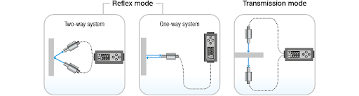
Fig 13. Optical pressure sensor modes
Installation and maintenance
How can use an Optical Pressure Sensor?
Using an optical pressure sensor involves several steps, including sensor installation, calibration (if necessary), data collection, and interpretation. Here's a general guide on how to use an optical pressure sensor:
- Sensor Selection: Choose the appropriate type of optical pressure sensor based on the application requirements, pressure range, sensitivity, and environmental conditions.
- Installation: Follow the manufacturer's guidelines for installing the sensor in the desired location. Ensure proper sealing, protection from environmental factors, and secure mounting to prevent any damage to the sensor.
- Calibration (If Required): Some optical pressure sensors might require calibration to establish a relationship between the measured optical signals and actual pressure values. Follow the calibration procedures provided by the sensor manufacturer or use a known pressure source to calibrate the sensor.
- Connection and Wiring: Connect the sensor to the necessary power source and data acquisition system using the appropriate cables and connectors. Optical pressure sensors may also require communication interfaces for data transfer and control.
- Data Collection: Initiate the data collection process by providing power to the sensor. The sensor will start measuring pressure-induced changes in optical properties and generate corresponding optical signals.
- Signal Processing: Capture the optical signals using a photodetector and transmit them to a signal processing system. This system can include electronics and software to process and analyze the signals.
- Data Interpretation: Use appropriate signal processing techniques to convert the optical signals into pressure values. This might involve demodulation, calibration curve application, and data analysis.
- Output Display or Storage: Display the pressure values on a digital screen, analog display, or a graphical user interface. Alternatively, store the data for further analysis, monitoring, or recording.
- Maintenance and Monitoring: Regularly inspect the sensor for signs of wear, damage, or malfunction. Ensure that the sensor's protective housing remains intact and that it's functioning as expected.
- Troubleshooting and Support: If you encounter any issues or unexpected behavior, consult the sensor's user manual, technical support, or manufacturer for assistance in troubleshooting.
It's important to note that the specific steps may vary depending on the type and model of the optical pressure sensor, as well as the intended application. Always refer to the manufacturer's documentation for detailed instructions specific to your sensor model. Proper installation, calibration, and maintenance are crucial to ensuring accurate and reliable pressure measurements over time.
Optical Pressure Sensor Calibration
Calibrating an optical pressure sensor involves establishing a relationship between the sensor's output (typically optical signals) and the actual pressure values being measured. Calibration ensures that the sensor provides accurate and reliable pressure readings. Here's a step-by-step guide on how to calibrate an optical pressure sensor:
- Preparation:
- Gather the necessary equipment, including a pressure reference standard, a controlled pressure source, and any calibration software or tools provided by the sensor manufacturer.
- Ensure that the sensor is properly installed and connected to the necessary power source and data acquisition system.
- Choose Calibration Points:
- Select a set of pressure points spanning the expected pressure range of the sensor's operation. Choose points that are representative of the application's operating conditions.
- Establish Baseline:
- Before applying pressure, record the initial optical signals or measurements provided by the sensor at each calibration point. This serves as a baseline reference.
- Apply Pressure:
- Use a controlled pressure source (pressure calibrator) to apply known pressures to the sensor. Ensure that the pressure source is accurate and properly calibrated.
- Record Measurements:
- As you apply each known pressure, record the corresponding optical signals or measurements provided by the sensor. These are the sensor's responses to the applied pressures.
- Create a Calibration Curve:
- Plot the recorded optical signals (sensor responses) against the corresponding known pressures. This plot is called a calibration curve or calibration graph.
- Curve Fitting and Equation:
- Fit a mathematical function (linear, polynomial, etc.) to the calibration curve. This function establishes the mathematical relationship between the optical signals and the actual pressures.
- Validation and Adjustment:
- Validate the calibration curve by comparing its predictions with data points that were not used in the calibration process. If necessary, adjust the curve-fitting parameters to improve accuracy.
- Apply Calibration:
- Once the calibration curve is validated and satisfactory, use the equation derived from the curve to convert future optical signals into accurate pressure values.
- Documentation:
- Document the calibration process, including the calibration points, calibration curve equation, any adjustments made, and the calibration date. This documentation is essential for traceability and quality control.
- Regular Maintenance:
- Periodically recalibrate the optical pressure sensor to account for any drift or changes in sensor performance over time. The frequency of recalibration depends on factors like sensor stability and the criticality of the application.
It's important to note that the calibration process may vary based on the sensor type, the manufacturer's recommendations, and the specific application. Some sensors may come with built-in self-calibration mechanisms or software tools to simplify the process. Always follow the manufacturer's guidelines and use appropriate calibration equipment to ensure accurate results.
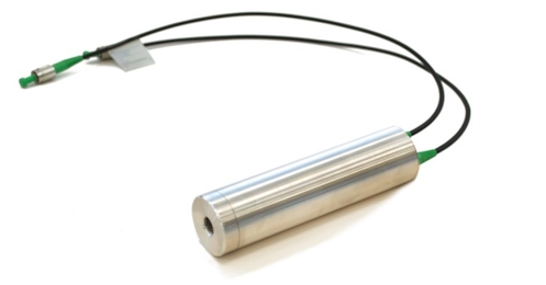
Fig 14. Optical pressure sensor
Optical Pressure Sensor accuracy
The accuracy of an optical pressure sensor refers to how closely the sensor's measured values align with the actual pressure values. It's a critical performance parameter that determines the reliability and quality of the pressure measurements. Optical pressure sensor accuracy can be influenced by several factors:
- Calibration: Proper calibration is essential for achieving accurate measurements. The sensor's output needs to be calibrated against a known pressure reference to establish a calibration curve or equation.
- Linearity: A sensor's linearity indicates how well its output follows a straight-line relationship with changes in pressure. A perfectly linear sensor would have a consistent change in output for each unit change in pressure.
- Hysteresis: Hysteresis refers to the difference in sensor output for the same pressure value when approached with increasing and decreasing pressure conditions. A high hysteresis value can lead to measurement errors.
- Repeatability: Repeatability is the ability of the sensor to produce consistent measurements when the same pressure is applied multiple times under similar conditions.
- Resolution: Resolution is the smallest change in pressure that a sensor can detect. A higher resolution allows the sensor to detect small pressure changes accurately.
- Sensitivity: Sensitivity indicates how much the sensor's output changes in response to a unit change in pressure. Higher sensitivity can lead to more accurate and precise measurements.
- Temperature Effects: Optical pressure sensors can be sensitive to temperature changes, which can impact the sensor's accuracy. Compensation techniques or temperature-stable designs can mitigate this effect.
- Environmental Interference: External factors such as electromagnetic interference (EMI) or vibration can affect the sensor's output and accuracy. Shielding and isolation techniques can help minimize interference.
- Sensor Design: The sensor's mechanical design, material properties, and sensing principle play a role in determining its accuracy. Proper design considerations can enhance accuracy.
- Signal Processing: Accurate signal processing techniques are crucial for extracting meaningful pressure information from the sensor's output signals.
When evaluating the accuracy of an optical pressure sensor, it's important to consider the sensor's specifications provided by the manufacturer. These specifications often include terms like "accuracy," "precision," "tolerance," and "error." For instance:
- Accuracy: This is a measure of how close the sensor's measurements are to the actual pressure values. It's often expressed as a percentage of the full-scale pressure range.
- Precision: Precision refers to the repeatability of measurements. A precise sensor produces consistent results even if they are not exactly accurate.
- Tolerance: Tolerance indicates the acceptable range of deviation from the true pressure value. A smaller tolerance value indicates higher accuracy.
- Error: Error is the difference between the sensor's measured value and the actual value. It's a key indicator of accuracy.
When selecting an optical pressure sensor, carefully review the manufacturer's accuracy specifications and consider the specific requirements of your application. Additionally, consider the calibration process, operating conditions, and environmental factors that might affect accuracy over time.
Optical Pressure Sensor Advantages and Disadvantages
Optical pressure sensors offer various advantages and disadvantages, which can influence their suitability for different applications. Here's an overview of the key advantages and disadvantages of optical pressure sensors:
Advantages:
- High Accuracy: Optical pressure sensors can offer high accuracy, making them suitable for applications that require precise pressure measurements.
- Wide Pressure Range: Depending on the sensor design, optical pressure sensors can cover a wide pressure range, from very low to very high pressures.
- Immunity to Electromagnetic Interference (EMI): Optical sensors are immune to electromagnetic interference, making them suitable for environments with high levels of EMI.
- Non-Intrusive: Many optical pressure sensors are non-intrusive, meaning they don't need to come into direct contact with the medium being measured. This can be beneficial for sensitive or hazardous materials.
- Long-Term Stability: Optical sensors can exhibit good long-term stability, maintaining their accuracy over extended periods.
- Compact Size: Many optical pressure sensors are compact, allowing for easy integration into various systems and applications.
- Multiplexing: Optical fibers can be multiplexed to enable the measurement of multiple points with a single fiber, reducing the need for extensive cabling.
- Remote Sensing: Optical fibers can transmit signals over long distances, enabling remote sensing in challenging or inaccessible locations.
- Intrinsically Safe: Some optical pressure sensors are intrinsically safe for use in hazardous environments, as they don't create sparks or electrical currents.
- Versatility: Optical pressure sensors can be used in various industries, including aerospace, oil and gas, medical, and more.
Disadvantages:
- Complex Calibration: Some optical pressure sensors require complex calibration procedures to establish accurate relationships between optical signals and pressure values.
- Temperature Effects: Temperature changes can impact the accuracy of optical pressure sensors, requiring temperature compensation techniques.
- Limited Sensitivity: Depending on the design, some optical sensors may have limited sensitivity compared to other pressure-sensing technologies.
- Higher Cost: Optical pressure sensors can be more expensive to manufacture and install compared to some other pressure sensor types.
- Fragility: Optical fibers can be delicate and prone to damage from bending, crushing, or excessive strain.
- Expertise Required: Proper installation, calibration, and maintenance of optical pressure sensors may require specialized knowledge and skills.
- Environmental Factors: Harsh environmental conditions such as extreme temperatures or humidity can affect the performance of optical sensors.
- Compatibility: Integrating optical sensors into existing systems may require compatibility with specific signal processing and data acquisition equipment.
- Limited to Certain Applications: Some optical pressure sensor types are more suitable for specific pressure ranges or applications, limiting their versatility.
- Data Processing: Processing optical signals into meaningful pressure values can require sophisticated signal processing techniques.
When selecting an optical pressure sensor for a specific application, it's important to consider both its advantages and disadvantages to ensure that it meets the requirements of the application and provides accurate and reliable measurements.
Fig 15. Optical pressure sensor usage
Important factors to choose the right Optical Pressure Sensor
Choosing the right optical pressure sensor for a specific application requires careful consideration of various factors. Here are the important factors to consider when selecting an optical pressure sensor:
- Pressure Range: Determine the range of pressures the sensor needs to measure. Ensure that the selected sensor covers the entire range of pressures relevant to your application.
- Accuracy Requirements: Assess the required accuracy and precision of pressure measurements. Consider the manufacturer's accuracy specifications and calibration processes.
- Type of Pressure: Identify whether the pressure to be measured is static, dynamic, or pulsating. Different sensor types may excel in different pressure variations.
- Environmental Conditions: Consider the environmental conditions the sensor will be exposed to, such as temperature, humidity, and exposure to chemicals or corrosive substances.
- Sensitivity: Evaluate the sensitivity of the sensor to ensure it can detect the desired pressure changes accurately.
- Physical Size and Form Factor: Determine whether the sensor's physical size and form factor are suitable for the installation space and integration requirements of your application.
- Installation and Mounting: Consider how the sensor needs to be installed and mounted. Some sensors may require specific mounting techniques or additional hardware.
- Compatibility: Check if the sensor's output and communication interfaces are compatible with your existing data acquisition and control systems.
- Calibration: Understand the calibration process required for the sensor. Determine if the sensor manufacturer provides calibration services or if you need to perform it yourself.
- Cost: Evaluate the sensor's cost, including initial purchase, installation, calibration, and maintenance costs, to ensure it fits within your budget.
- Application Industry: Consider the specific industry or field of application (aerospace, oil, and gas, medical, etc.) to choose a sensor that is designed for the relevant environmental and operational conditions.
- Reliability and Longevity: Assess the sensor's expected lifespan and long-term reliability. Opt for sensors that have demonstrated durability and stability over time.
- Ease of Integration: Determine how easily the sensor can be integrated into your existing systems or equipment, including compatibility with connectors and interfaces.
- Maintenance Requirements: Understand the maintenance needs of the sensor, including recalibration frequency and any special care instructions.
- Technical Support: Consider the availability of technical support and assistance from the sensor manufacturer, especially if the sensor's operation is complex.
- Data Processing: Evaluate the complexity of signal processing required to convert the sensor's output into meaningful pressure values. Ensure you have the necessary tools and expertise.
- Certifications and Standards: Check if the sensor meets industry standards and certifications that are relevant to your application.
- Future Scalability: Consider whether the sensor's capabilities align with potential future needs or expansion of your application.
By carefully assessing these factors and conducting thorough research, you can select the optical pressure sensor that best meets the requirements of your application, ensuring accurate and reliable pressure measurements.
Top Brands of Optical Pressure Sensors
There are several reputable brands known for producing high-quality optical pressure sensors. Here are some of the top brands in the field of optical pressure sensing:
- Honeywell Sensing and Productivity Solutions: Honeywell offers a wide range of sensors, including optical pressure sensors, for various applications in industries such as aerospace, industrial automation, and transportation.
- FISO Technologies Inc.: FISO is a leading manufacturer of fiber optic sensors, including optical pressure sensors. They offer sensors for medical, industrial, and scientific applications.
- Opsens Solutions Inc.: Opsens specializes in fiber optic sensors for various industries, including medical, energy, and industrial applications. They provide pressure sensors based on Fabry-Perot technology.
- Sensuron: Sensuron focuses on distributed sensing solutions based on optical fiber technology. Their sensors find applications in aerospace, structural health monitoring, and research.
- Micron Optics, Inc.: Micron Optics is known for its optical sensing solutions, including pressure sensors based on Fiber Bragg Grating (FBG) technology. They serve industries like aerospace, energy, and civil engineering.
- Fotech Solutions: Fotech Solutions specializes in distributed fiber optic sensing solutions for industries such as oil and gas, security, and infrastructure monitoring.
- Omega Engineering, Inc.: Omega offers a variety of sensors, including optical pressure sensors, for industrial applications. They provide sensors for process control, automation, and research.
- Opsytec Dr. Gröbel GmbH: Opsytec provides optical pressure sensors based on Fabry-Perot and micro bend technologies. They cater to applications in industrial process monitoring and research.
- Smartec SA: Smartec focuses on fiber optic sensing solutions, including optical pressure sensors. Their sensors find use in industries like oil and gas, civil engineering, and environmental monitoring.
- Prime Photonics: Prime Photonics specializes in advanced optical sensors, including pressure sensors, for applications in industries like aerospace, power generation, and defense.
When selecting a brand of optical pressure sensor, it's important to thoroughly research the brand's reputation, product offerings, customer reviews, and alignment with your specific application requirements. Additionally, consider factors such as technical support, warranties, and compatibility with your existing systems.
Conclusion
Optical pressure sensors are advanced devices that offer accurate and reliable pressure measurements using optical principles. They find applications in a wide range of industries, from aerospace and oil and gas to biomedical and environmental monitoring. These sensors utilize various technologies like Fiber Bragg Gratings (FBGs), Fabry-Perot interferometry, microbend fibers, and distributed fiber optics to convert pressure-induced changes into optical signals.
The advantages of optical pressure sensors include high accuracy, wide pressure range, immunity to electromagnetic interference, and compact size. They can be non-intrusive, offer long-term stability, and are suitable for remote sensing. However, they also have challenges, such as complex calibration processes, sensitivity to temperature, and higher costs compared to some other sensor types.
Selecting the right optical pressure sensor involves considering factors like pressure range, accuracy requirements, environmental conditions, physical size, compatibility, calibration, and maintenance needs. It's essential to assess both the advantages and disadvantages of the sensor, as well as the reputation of the brand producing it.
In conclusion, optical pressure sensors are valuable tools that contribute to accurate pressure measurements in various critical applications. Their advanced technology and versatility make them an attractive choice for industries seeking precision and reliability in pressure sensing. Careful consideration of the factors discussed in this conversation will help you choose the right optical pressure sensor for your specific needs.
To recap
Q1: What is an optical pressure sensor?
An optical pressure sensor is a device that measures pressure by utilizing changes in optical properties, such as light intensity or wavelength, caused by pressure-induced deformations in a sensing element. These sensors offer accurate and reliable pressure measurements across various industries.
Q2: How do optical pressure sensors work?
Optical pressure sensors work based on the principle that pressure-induced deformations in a sensing element lead to changes in optical properties. These changes are converted into optical signals that can be processed to determine the corresponding pressure values.
Q3: What are the advantages of optical pressure sensors?
- High accuracy
- Wide pressure range
- Immunity to electromagnetic interference (EMI)
- Non-intrusive measurements
- Long-term stability
- Compact size and versatile applications
Q4: What are the disadvantages of optical pressure sensors?
- Complex calibration processes
- Sensitivity to temperature variations
- Limited sensitivity in some cases
- Higher costs compared to some other sensor types
- Fragility of optical fibers
Q5: Where are optical pressure sensors used?
Optical pressure sensors are used in various applications, including aerospace, oil and gas, medical devices, industrial automation, automotive, environmental monitoring, structural health monitoring, and research.
Q6: How accurate are optical pressure sensors?
The accuracy of optical pressure sensors varies depending on the sensor's design, calibration, and application. They can offer high accuracy, often within a certain percentage of the full-scale pressure range.
Q7: How are optical pressure sensors calibrated?
Optical pressure sensors are calibrated by establishing a relationship between their output (optical signals) and known pressure values. This involves applying known pressures to the sensor and recording the corresponding optical signals to create a calibration curve or equation.
Q8: What factors should I consider when choosing an optical pressure sensor?
Important factors include pressure range, accuracy requirements, environmental conditions, sensitivity, physical size, compatibility, calibration procedures, maintenance needs, and the reputation of the brand producing the sensor.
Q9: Can optical pressure sensors be used in harsh environments?
Yes, some optical pressure sensors are designed to withstand harsh environments, but environmental conditions such as extreme temperatures, humidity, and exposure to chemicals should be considered during sensor selection.
Q10: Are optical pressure sensors suitable for remote sensing?
Yes, optical pressure sensors can be suitable for remote sensing due to their ability to transmit optical signals over long distances using optical fibers.
Q11: How often should optical pressure sensors be recalibrated?
Recalibration frequency depends on the sensor's stability and the criticality of the application. In some cases, annual recalibration might be necessary, while other sensors may require less frequent recalibration.
Q12: What types of pressure can optical sensors measure?
Optical pressure sensors can measure static pressure, dynamic pressure, and even rapidly changing pressure variations, depending on the sensor's design and technology.
Q13: Can optical pressure sensors be used in hazardous environments?
Yes, some optical pressure sensors are intrinsically safe and suitable for use in hazardous environments where sparks or electrical currents could pose a risk.
References
https://www.te.com/usa-en/products/sensors/optical-sensors.html
https://forumautomation.com/t/fiber-optic-pressure-sensors/3149
https://www.researchgate.net/figure/Schematic-of-the-FBG-pressure-sensor_fig2_331056801
https://www.micro-epsilon.in/fiber-optic-sensors/
https://lunainc.com/product/os9200
https://www.researchgate.net/figure/Basic-microbend-fiber-optic-sensor_fig2_313893480
https://www.esa.int/ESA_Multimedia/Images/2010/04/Optical_MEMS_gas_sensor
https://pubs.acs.org/doi/10.1021/acssensors.7b00961
Recent Posts
-

Booster Pump Troubleshooting and Maintenance: How to Fix and Prevent Common Issues
1. Introduction Imagine turning on your faucet only to be greeted with a weak trickle of water when …22nd Apr 2025 -

Energy-Efficient Booster Pumps: Selection and Tips for Maximizing Performance
1. Introduction Imagine never having to deal with fluctuating water pressure, noisy pumps, or skyroc …19th Apr 2025 -

Booster Pumps for Sustainable Water Systems: Irrigation and Rainwater Harvesting Solutions
1. Introduction Water scarcity is no longer a distant threat—it’s a reality affecting millions …16th Apr 2025