

Types Of Load Cell Based On Technology
Do you ever wonder how industries accurately measure the forces that shape our world? From weighing massive cargo containers to ensuring the structural integrity of bridges, the answer lies in a small but mighty device known as the load cell. With its ability to transform mechanical force into precise electrical signals, the load cell plays a vital role in industries ranging from manufacturing to aerospace. Join me as we delve into the fascinating world of load cells and uncover the remarkable science behind their incredible power to measure and control forces with unwavering accuracy.
Types Of Load Cells Based On Technology
- Strain Gauge Load Cells: Strain gauge load cells are the most common and widely used type. They utilize strain gauges, which are bonded to the load cell structure. The strain gauges measure the deformation of the structure when a force is applied, and this deformation is converted into an electrical signal.
- Hydraulic Load Cells: Hydraulic load cells work on the principle of fluid pressure. They consist of a piston-cylinder arrangement filled with fluid. When a force is applied, it compresses the fluid, and the resulting pressure change is measured to determine the applied force.
- Pneumatic Load Cells: Pneumatic load cells also rely on fluid pressure but use air instead of liquid. They operate by measuring the change in air pressure caused by the applied force. Pneumatic load cells are commonly used in applications where high accuracy and sensitivity are required.
- Capacitive Load Cells: Capacitive load cells utilize the variation in capacitance between two plates as the applied force causes them to move closer or farther apart. The change in capacitance is then converted into an electrical signal, providing a measure of the applied force.
- Piezoelectric Load Cells: Piezoelectric load cells employ the piezoelectric effect, where certain materials generate an electrical charge when subjected to mechanical stress. When a force is applied, the piezoelectric material generates an electrical signal proportional to the applied force.
- Magnetic Load Cells: Magnetic load cells use the principles of magnetic induction to measure force. They consist of a magnet and a coil, and the applied force causes a change in the magnetic field, inducing a voltage in the coil. This voltage is then measured to determine the force.
Each type of load cell has its advantages and is suitable for specific applications based on factors such as accuracy requirements, environmental conditions, and cost considerations.
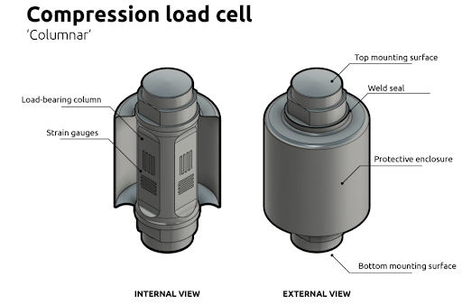
Fig 1. Compression load cell
What is a Strain Gauge Load Cell?
A strain gauge load cell is a type of load cell that utilizes strain gauge technology to measure force or weight accurately. It is the most common and widely used type of load cell due to its reliability, precision, and cost-effectiveness.
The key component of a strain gauge load cell is the strain gauge itself. A strain gauge is a thin strip or wire made of a conductive material, such as metal or semiconductor. It is bonded to the load cell structure in a specific pattern.
When a force is applied to the load cell, it deforms the structure, causing a change in its shape. This deformation leads to the stretching or compression of the strain gauge. As a result, the electrical resistance of the strain gauge changes in proportion to the applied force.
To measure this change in resistance, the strain gauge is connected in a Wheatstone bridge configuration, which is an electrical circuit that balances the resistance of the strain gauge with other resistors. When a force is applied, the imbalance in the bridge causes a small electrical signal, known as the output signal, to be generated.
The output signal is typically in the form of a low-level voltage or current, which can be further amplified and conditioned for accurate measurement. Signal conditioning equipment is often used to increase signal strength, filter out noise, and provide a usable output for data acquisition or control systems.
Strain gauge load cells offer several advantages. They provide high accuracy and resolution, making them suitable for applications that require precise force or weight measurements. They also have a wide measurement range, allowing them to handle both small and large loads. Additionally, strain gauge load cells are compact, durable, and relatively cost-effective compared to other types of load cells.
Overall, strain gauge load cells are an essential and versatile tool used in various industries, such as manufacturing, logistics, automotive, aerospace, and more, where precise force measurement is crucial for quality control, safety, and process optimization.
How is the structure of Strain Gauge Load Cells?
The structure of a strain gauge load cell typically consists of the following components:
- Load Cell Body: The load cell body is the main structural element of the load cell. It is usually made of a durable material such as stainless steel or alloy steel, chosen for its strength and resistance to environmental factors. The load cell body is designed to handle the forces and loads applied to it while maintaining its structural integrity.
- Strain Gauges: Strain gauges are the essential sensing elements of a strain gauge load cell. They are thin strips or wires made of a conductive material, such as metal or semiconductor. The strain gauges are bonded to specific areas on the load cell body where the maximum strain is expected to occur when a force is applied. These areas are typically referred to as the "gauging points" or "measurement points."
- Wheatstone Bridge: The strain gauges are connected in a Wheatstone bridge configuration, which is an electrical circuit used to measure small changes in resistance. The Wheatstone bridge consists of four resistive arms, with the strain gauges forming two of these arms. The bridge is balanced when no force is applied, resulting in a zero output signal.
- Load-Receiving Element: The load-receiving element is part of the load cell that directly interacts with the force being measured. It is typically a structure or component designed to support and distribute the applied force across the strain gauges. The load-receiving element can take various forms depending on the application, such as a platform, beam, or rod.
- Output Connector: The load cell has an output connector through which the electrical signal generated by the strain gauges is transmitted. The connector allows the load cell to be easily connected to instrumentation or data acquisition systems for further processing and analysis of the output signal.
- Protective Coating: Some strain gauge load cells may have a protective coating or cover to shield the internal components from environmental factors such as moisture, dust, or corrosive substances. This coating helps to prolong the lifespan of the load cell and maintains its accuracy and reliability.
Overall, the structure of a strain gauge load cell is designed to accurately measure forces by converting mechanical deformation into electrical signals. The careful selection and arrangement of components ensure that the load cell can withstand the applied forces while providing precise and consistent measurements.
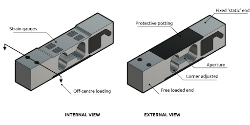
Fig 2. Strain gauge
How does a Strain Gauge Load Cell work?
A strain gauge load cell works based on the principle of the strain gauge effect, which states that the electrical resistance of a conductor changes when it undergoes mechanical deformation. Here's how a strain gauge load cell functions:
- Mechanical Deformation: When a force is applied to the load cell, it deforms the load-receiving element or structure of the load cell. This deformation causes the strain gauge, which is bonded to the load cell structure, to stretch or compress.
- Change in Resistance: The deformation of the strain gauge leads to a change in its electrical resistance. When the strain gauge stretches, its length increases, increasing resistance (tensile strain). Conversely, when the strain gauge compresses, its length decreases, leading to a decrease in resistance (compressive strain). This change in resistance is proportional to the applied force.
- Wheatstone Bridge Circuit: The strain gauge is part of a Wheatstone bridge circuit. The Wheatstone bridge consists of four resistive arms, with the strain gauge forming one or two of these arms. The other arms typically consist of precision resistors.
- Output Signal Generation: When the strain gauge deforms and changes resistance, it causes an imbalance in the Wheatstone bridge circuit. This imbalance results in a small electrical signal known as the output signal.
- Signal Conditioning: The output signal from the Wheatstone bridge circuit is typically very small and requires amplification and conditioning for further processing. Signal conditioning equipment, such as amplifiers, filters, and analog-to-digital converters, is used to strengthen and refine the output signal.
- Output Measurement: The conditioned output signal can then be measured and interpreted as a measure of the applied force. This measurement can be displayed on instrumentation systems, data acquisition systems, or used for control purposes, depending on the specific application.
By measuring the change in resistance of the strain gauge, a strain gauge load cell accurately converts the applied force into an electrical signal that can be quantified and utilized for various force or weight measurement applications.
It's worth noting that the sensitivity and accuracy of a strain gauge load cell depend on factors such as the number and arrangement of strain gauges, the material properties of the load cell structure, and the precision of the Wheatstone bridge circuit. Calibration and careful design considerations are crucial to ensure the load cell's reliable and accurate performance.
- Gauge Factor
Each strain gauge has a distinct strain sensitivity, which is quantified by the gauge factor (GF). The gauge factor is the fractional change in electrical resistance ratio to the fractional change in length. It is a gauge sensitivity measure (GF is commonly about 2) for metallic strain gauges.
Small Changes in Strain
Each strain gauge has a distinct strain sensitivity, which is quantified by the gauge factor (GF). The gauge factor is the fractional change in electrical resistance ratio to the fractional change in length. It is a gauge sensitivity measure (GF is commonly about 2) for metallic strain gauges.
After establishing a strain gauge load cell and measuring the resulting change in resistance, we conclude that everything is functioning OK. Wait up and do not act too quickly. Strain measurements are usually limited to a few millistrain (e \cdot 10^{-3})(fancy units for strain, but still very small).
For example, suppose you apply a strain of 500µε. An electrical resistance change for a strain gauge with a gauge factor of 2 is limited to:
2 * (500 * 10-6) = 0.1%
This is a 0.12-charge for a gauge reading of 120Ω.0.12 is an extremely little change that, for most equipment, cannot even be detected, let alone accurately measured. Therefore, we will need a new device that can accurately measure tiny resistance changes that are costly. Or a device that can convert these extreme changes in resistance into a form that can be precisely measured.
- Amplifiers and Wheatstone Bridge
Using a Wheatstone bridge is a valuable method to take minute changes in resistance and convert them into a more measurable value. A Wheatstone bridge is a four-resistor configuration with a known voltage applied as follows:
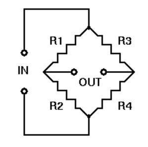
Fig 3. Wheatstone Bridge
Where Vin represents a constant voltage, the output Vout is calculated. Vout is 0 if R1/R2 = R3/R4; however, if the value of one of the resistors changes, Vout will vary in a way that can be measured. This change is regulated by the following equation based on Ohm's law:
Vout = [(R3/(R3 + R4) - R2/(R1 + R2))] * Vin
We can measure the change in Vout by substituting one of the resistors in a Wheatstone bridge with a strain gauge. We can then use this information to determine the amount of the applied force.
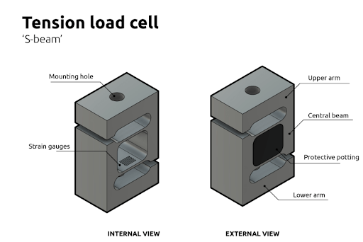
Fig 4. Tension load cell
What are the Strain Gauge Load Cells types?
Strain gauge load cells come in various types, each suited for specific applications based on their design, shape, and mounting arrangement. Here are some common types of strain gauge load cells:
- Compression Load Cells: Compression load cells are designed to measure forces when the load is applied in compression. They have a compact and robust structure and are often used in applications such as industrial weighing, tank and silo weighing, and material testing.
- Tension Load Cells: Tension load cells are used to measure forces in tension or pulling applications. They are commonly used in crane scales, force measurement in cables or ropes, and other applications where the load is suspended.
- Universal Load Cells: Universal load cells, also known as "bending beam load cells," can measure both compression and tension forces. They are versatile and widely used in industrial weighing, packaging equipment, and material handling systems.
- Shear Beam Load Cells: Shear beam load cells feature a shear-type sensing element that measures the shear strain produced by the applied force. They are commonly used in platform scales, conveyor systems, and other applications requiring accurate weighing of large objects.
- S-Type Load Cells: S-type load cells, also called "S-beam load cells," have an S-shaped design and can measure both tension and compression forces. They are versatile and used in applications such as force testing machines, hoist and crane scales, and belt scales.
- Pancake Load Cells: Pancake load cells have a flat, disk-like shape and can measure forces in compression. They are commonly used in applications with limited vertical space, such as in testing machines, robotics, and industrial automation.
- Canister Load Cells: Canister load cells have a cylindrical or canister-like shape and can handle high-capacity loads. They are suitable for applications such as tank and hopper weighing, truck scales, and heavy industrial weighing.
These are just a few examples of strain gauge load cell types. Each type has its unique design and characteristics that make it suitable for specific force measurement applications. It's essential to select the appropriate type based on the application requirements, load capacity, mounting considerations, and environmental conditions.
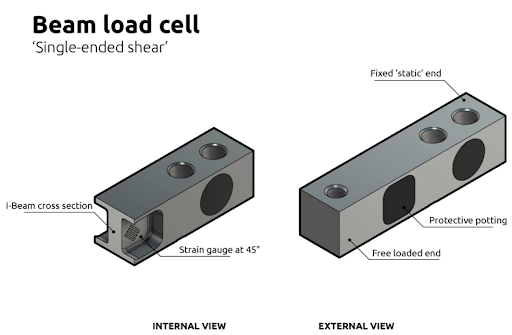
Fig 5. Beam load cell
What is a Hydraulic Load Cell?
A hydraulic load cell is a type of load cell that utilizes the principle of fluid pressure to measure force or weight accurately. It operates based on Pascal's law, which states that when pressure is applied to a fluid, it is transmitted equally in all directions.
A typical hydraulic load cell consists of a piston and cylinder arrangement filled with hydraulic fluid, such as oil or water. The piston is attached to the load-receiving element, while the cylinder is fixed to the load-bearing structure.
When a force is applied to the load cell, it causes the load-receiving element to move, resulting in the compression of the hydraulic fluid within the cylinder. This compression leads to an increase in fluid pressure, which is proportional to the applied force.
The change in fluid pressure is then measured using a pressure transducer or a pressure gauge connected to the load cell. This measurement indicates the force or weight being applied.
Hydraulic load cells offer several advantages. They provide excellent accuracy and linearity, making them suitable for applications that require precise force measurements. They also have a high overload capacity, meaning they can withstand and accurately measure forces that exceed their rated capacity without damage. Additionally, hydraulic load cells are known for their robustness and durability, making them suitable for harsh environments.
However, hydraulic load cells also have some limitations. They require a fluid-filled system, which can be prone to leaks and may require periodic maintenance. They also have a slower response time compared to some other load cell types.
Hydraulic load cells find applications in various industries, including heavy machinery, automotive, construction, material testing, and industrial weighing. Their ability to accurately measure large forces makes them ideal for heavy-duty applications where high capacities and ruggedness are required.
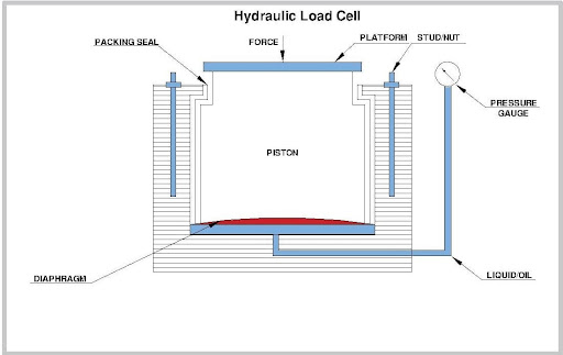
Fig 6. Hydraulic load cell
Hydraulic Load Cell's internal parts and Structure
Hydraulic load cells utilize fluid pressure to measure forces. The internal parts and structure of a hydraulic load cell typically consist of the following components:
- Load-Receiving Element: The load-receiving element is part of the load cell that directly interacts with the force being measured. It is typically a piston or diaphragm that deforms under the applied force. The load-receiving element transfers the force to the fluid inside the load cell.
- Fluid Chamber: The fluid chamber houses the hydraulic fluid that transmits the force from the load-receiving element to the pressure-sensing mechanism. It is typically filled with oil or another suitable hydraulic fluid that is non-compressible.
- Pressure Transducer: The pressure transducer, also known as a pressure sensor or pressure gauge, is responsible for converting fluid pressure into an electrical signal. It is located within the load cell and detects the pressure exerted by the hydraulic fluid.
- Fluid Lines and Connectors: Hydraulic load cells have fluid lines and connectors that allow the flow of hydraulic fluid between the load-receiving element, fluid chamber, and pressure transducer. These components ensure that the force applied to the load-receiving element is accurately transmitted to the pressure-sensing mechanism.
- Output Connector: The load cell has an output connector through which the electrical signal generated by the pressure transducer is transmitted. The connector allows the load cell to be easily connected to instrumentation or data acquisition systems for further processing and analysis of the output signal.
- Protective Enclosure: Some hydraulic load cells may have a protective enclosure or housing to safeguard the internal components from external environmental factors. This enclosure helps to prevent contamination, moisture ingress, and physical damage to the load cell.
The structure and internal components of hydraulic load cells may vary depending on the specific design and application requirements. However, the fundamental principle remains the same: the applied force is transferred to a hydraulic fluid, and the resulting pressure is measured and converted into an electrical signal for force measurement purposes.
It is important to note that hydraulic load cells require appropriate hydraulic fluid maintenance, such as regular checks, fluid level adjustments, and contamination prevention, to ensure accurate and reliable performance.
Hydraulic Load Cells Working Principle
The working principle of a hydraulic load cell is based on Pascal's law, which states that pressure applied to a fluid in a confined space is transmitted equally in all directions.
Here's how a hydraulic load cell works:
- Force Application: When an external force is applied to the load-receiving element of the hydraulic load cell, such as a piston or diaphragm, it deforms under the force. The load-receiving element acts as a mechanical interface between the force and the hydraulic fluid.
- Fluid Pressure Generation: As the load-receiving element deforms, it displaces the hydraulic fluid present within the load cell. This displacement causes an increase in fluid pressure proportional to the applied force. The hydraulic fluid, usually oil, is incompressible, so the pressure generated is directly proportional to the force being measured.
- Pressure Transmission: The increased fluid pressure is transmitted through the fluid lines and connectors within the load cell to the pressure transducer or pressure sensing mechanism.
- Pressure Measurement: The pressure transducer, typically a strain gauge or piezoelectric sensor, detects the fluid pressure and converts it into an electrical signal. The pressure sensing mechanism may involve the deformation of strain gauges or the generation of an electrical charge in the case of a piezoelectric sensor.
- Electrical Output: The electrical signal generated by the pressure transducer is typically in the form of voltage or current and is proportional to the applied force. This signal can be further amplified, conditioned, and processed for measurement, control, or data acquisition purposes.
- Force Measurement: The electrical output signal from the pressure transducer is calibrated and scaled to provide an accurate measurement of the applied force. The calibrated signal can be displayed on instrumentation systems, recorded in data acquisition systems, or used for control purposes, depending on the specific application requirements.
By utilizing the principles of hydraulic fluid pressure transmission, hydraulic load cells offer accurate and reliable force measurement capabilities. The hydraulic fluid acts as a medium to transfer the applied force to the pressure-sensing mechanism, where it is converted into an electrical signal for further analysis and utilization.
It's important to note that hydraulic load cells require proper maintenance, including regular fluid checks, calibration, and protection against contamination, to ensure optimal performance and accurate force measurement.
Hydraulic Load Cells Types
There are different types of hydraulic load cells, each designed to suit specific applications and force measurement requirements. Here are some common types of hydraulic load cells:
- Piston-Type Hydraulic Load Cells: These load cells consist of a piston that moves within a chamber filled with hydraulic fluid. The applied force causes the piston to displace the fluid, generating a pressure that is proportional to the force. Piston-type load cells are known for their high accuracy and durability, making them suitable for heavy-duty applications.
- Diaphragm-Type Hydraulic Load Cells: Diaphragm load cells use a flexible diaphragm that deforms under the applied force, resulting in a change in hydraulic pressure. The diaphragm separates the hydraulic fluid from the force application, making it ideal for applications where the fluid and force need to be isolated, such as in corrosive or high-temperature environments.
- Ring-Type Hydraulic Load Cells: These load cells consist of a ring-shaped sensing element that deforms under the applied force. The force-induced deformation causes the hydraulic fluid to generate pressure, which is measured to determine the force. Ring-type load cells are commonly used in applications where the load needs to be applied radially or circumferentially, such as in tank weighing or bolt tensioning.
- Bellow-Type Hydraulic Load Cells: Bellow load cells use a flexible metal bellow that expands or contracts in response to the applied force. The movement of the bellow displaces the hydraulic fluid, resulting in a change in pressure that is measured to determine the force. Bellow load cells are suitable for applications where high sensitivity and compact size are required.
- Single Point Hydraulic Load Cells: Single point load cells are designed for applications that require weighing or force measurement at a single point of contact. They typically consist of a hydraulic load cell combined with a weighing platform or support structure, allowing accurate measurement of loads applied at a specific location.
These are just a few examples of hydraulic load cell types, and variations exist within each category to cater to specific force measurement needs. The selection of the appropriate hydraulic load cell type depends on factors such as the application requirements, load capacity, environmental conditions, and desired accuracy.
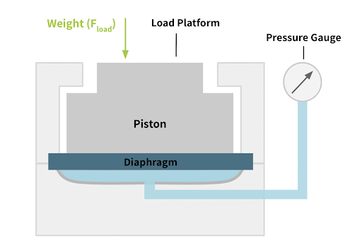
Fig 7. Hydraulic Load Cell Diagram
What are Pneumatic Load Cells?
A pneumatic load cell is a type of load cell that uses compressed air or gas to measure forces. It operates based on the principle of pressure changes in a confined chamber caused by the applied force.
Here's how a pneumatic load cell works:
- Load Application: When an external force is applied to the load-receiving element of the pneumatic load cell, it deforms or moves under the force. The load-receiving element may be a diaphragm, bellows, or piston, depending on the design of the load cell.
- Air or Gas Pressure Changes: The deformation of the load-receiving element causes a change in the volume of the confined chamber within the load cell. As the volume changes, the pressure of the compressed air or gas inside the chamber also changes.
- Pressure Measurement: The pressure changes are measured using a pressure transducer, such as a pressure sensor or manometer, that is connected to the confined chamber. The pressure transducer detects the variations in pressure and converts them into an electrical signal.
- Electrical Output: The electrical signal generated by the pressure transducer is proportional to the applied force. It can be further amplified, conditioned, and processed for accurate force measurement and data acquisition.
- Force Measurement: The electrical output signal is calibrated and scaled to provide an accurate measurement of the applied force. The calibrated signal can be displayed on instrumentation systems, recorded in data acquisition systems, or used for control purposes, depending on the application requirements.
Pneumatic load cells offer several advantages, including high accuracy, stability, and resistance to electromagnetic interference. They are often used in applications where hydraulic load cells are not suitable, such as in environments where the presence of liquids or hydraulic fluids is undesirable.
Pneumatic load cells find applications in various industries, including aerospace, automotive, manufacturing, and materials testing. They are commonly used in force measurement applications where high precision, reliability, and resistance to environmental factors are essential.
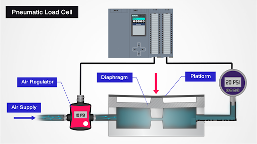
Fig 8. Pneumatic load cells
What are the Pneumatic Load Cell's internal components?
Pneumatic load cells consist of several internal components that work together to measure forces using compressed air or gas. The specific components may vary depending on the design and construction of the load cell, but here are the common internal components found in pneumatic load cells:
- Load-Receiving Element: The load-receiving element is part of the load cell that directly interacts with the applied force. It can be a diaphragm, bellows, or piston, depending on the design. The load-receiving element deforms or moves under the force, causing changes in the internal pressure of the load cell.
- Confined Chamber: The confined chamber is a sealed cavity within the load cell that houses the compressed air or gas. It is connected to the load-receiving element, and changes in the volume of the chamber occur as the load-receiving element deforms under the applied force.
- Pneumatic Line or Tubing: Pneumatic load cells have lines or tubing that connect the confined chamber to the pressure measurement system. These lines allow the transfer of compressed air or gas pressure changes from the load cell to the pressure transducer.
- Pressure Transducer: The pressure transducer is a component that measures the changes in pressure within the load cell and converts them into an electrical signal. It may consist of a pressure sensor, manometer, or other pressure-sensing mechanism. The pressure transducer is typically connected to the pneumatic lines or tubing to monitor the pressure changes accurately.
- Electrical Output Connector: The load cell has an electrical output connector through which the electrical signal generated by the pressure transducer is transmitted. The output connector allows the load cell to be easily connected to instrumentation or data acquisition systems for further processing and analysis of the output signal.
- Protective Enclosure: Some pneumatic load cells may have a protective enclosure or housing that covers and protects the internal components. This enclosure helps shield the load cell from external environmental factors and physical damage, ensuring its longevity and accuracy.
These are the basic internal components of a pneumatic load cell. The precise design and arrangement of these components may vary depending on the specific load cell model and manufacturer. The interaction of these components enables the load cell to accurately measure forces using the principles of pneumatic pressure changes.
How is the Pneumatic Load Cells operation?
The operation of a pneumatic load cell involves the following steps:
- Load Application: The pneumatic load cell is placed in a position where it will receive the applied force. The force can be applied directly to the load cell or transmitted through a load-transmitting element such as a platform or hook.
- Deformation of Load-Receiving Element: The applied force causes the load-receiving element of the pneumatic load cell to deform or move. The load-receiving element can be a diaphragm, bellows, or piston, depending on the design of the load cell.
- Pressure Change in Confined Chamber: The deformation of the load-receiving element results in a change in the volume of the confined chamber within the load cell. If the load-receiving element moves outward, it increases the volume of the chamber. Conversely, if it moves inward, it decreases the volume of the chamber.
- Compressed Air or Gas Pressure Changes: The change in the volume of the confined chamber leads to a corresponding change in the pressure of the compressed air or gas within the load cell. When the chamber volume increases, the pressure decreases, and when the chamber volume decreases, the pressure increases.
- Pressure Measurement: The pressure changes inside the load cell are measured using a pressure transducer, which can be a pressure sensor or manometer. The pressure transducer detects the variations in pressure and converts them into an electrical signal.
- Electrical Output: The electrical signal generated by the pressure transducer is proportional to the applied force. It is typically a voltage or current signal and can be further amplified, conditioned, and processed as needed for accurate force measurement and data acquisition.
- Force Measurement: The electrical output signal is calibrated and scaled to provide an accurate measurement of the applied force. The calibration ensures that the electrical signal corresponds to the actual force being applied. The calibrated signal can be displayed on instrumentation systems, recorded in data acquisition systems, or used for control purposes, depending on the application requirements.
The overall operation of a pneumatic load cell relies on the principle that the applied force causes a deformation in the load-receiving element, which in turn changes the internal pressure of the load cell. By measuring these pressure changes, the load cell can determine the magnitude of the applied force.
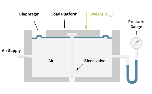
Fig 9. Pneumatic Load Cell Diagram
What are the Pneumatic Load Cells types?
There are different types of pneumatic load cells, each designed for specific applications and load measurement requirements. Here are some common types of pneumatic load cells:
- Diaphragm-Type Pneumatic Load Cells: Diaphragm-type pneumatic load cells use a flexible diaphragm as the load-receiving element. The diaphragm deforms under the applied force, causing changes in the internal pressure of the load cell. These load cells are known for their high accuracy and sensitivity, making them suitable for applications that require precise force measurement.
- Bellows-Type Pneumatic Load Cells: Bellows-type pneumatic load cells feature a bellows-shaped load-receiving element. The bellows expand or contract in response to the applied force, resulting in pressure changes within the load cell. These load cells offer excellent durability and resistance to environmental conditions, making them suitable for harsh industrial environments.
- Piston-Type Pneumatic Load Cells: Piston-type pneumatic load cells use a piston as the load-receiving element. The applied force causes the piston to move within a confined chamber, leading to pressure changes. These load cells are commonly used in applications that require high load capacity and robust construction, such as heavy machinery and industrial weighing.
- Differential-Pressure Pneumatic Load Cells: Differential pressure pneumatic load cells measure the difference in pressure between two chambers within the load cell. The applied force causes pressure imbalances, which are detected and measured to determine the force. These load cells are suitable for applications where both tension and compression forces need to be measured accurately.
- Single-Ended Pneumatic Load Cells: Single-ended pneumatic load cells have one end fixed, while the other end is subjected to the applied force. The load cell measures the pressure changes caused by the force, providing accurate force measurement. These load cells are commonly used in weighing applications and force monitoring systems.
- Double-Ended Pneumatic Load Cells: Double-ended pneumatic load cells have both ends exposed to the applied force. The load cell measures the pressure changes at both ends, allowing for precise force measurement and eliminating errors caused by side loads. These load cells are often used in tension-compression force measurement applications.
The choice of pneumatic load cell type depends on factors such as the required load capacity, accuracy, environmental conditions, and specific application requirements. It's important to select the appropriate type of pneumatic load cell that best suits the intended application to ensure accurate and reliable force measurement.
Capacitive Load Cells
Capacitive load cells are a type of load cell that uses the principle of capacitance to measure the applied force. They utilize changes in the electrical capacitance between two or more plates to determine the force exerted on the load cell. Here's an overview of capacitive load cells:
Working Principle: Capacitive load cells consist of two or more plates separated by a small gap. When an external force is applied to the load cell, the plates undergo deformation, causing a change in the distance between them. This change in distance alters the capacitance between the plates.
Capacitance Measurement: The capacitance between the plates is measured using an electrical circuit. The load cell's electronics apply an electrical voltage to the plates, and the resulting capacitance is detected and converted into an electrical signal. This signal is proportional to the applied force and is typically calibrated to provide accurate force measurements.
Capacitive load cells are commonly used in applications such as industrial weighing systems, force monitoring in manufacturing processes, material testing, and laboratory research. Their high accuracy, wide load range, and fast response time make them suitable for various force measurement needs.
Capacitive Load Cells working operation
The working operation of a capacitive load cell involves the following steps:
- Construction: Capacitive load cells consist of two or more plates, typically made of conductive materials such as metal, separated by a small gap. One plate is fixed, while the other plate(s) are subjected to the applied force.
- Capacitance Measurement: An electrical circuit is connected to the plates of the load cell. The circuit applies an electrical voltage or charge to the plates, creating an electric field between them. The capacitance is the ability of the plates to store electrical charge, and it depends on the distance between the plates.
- Force Application: When an external force is applied to the load cell, the plates undergo deformation. The deformation causes a change in the distance between the plates. As the distance changes, the capacitance between the plates also changes.
- Capacitance Detection: The electrical circuit measures the capacitance between the plates. This is done using techniques such as impedance or frequency measurement. The change in capacitance is detected and converted into an electrical signal.
- Electrical Signal Processing: The electrical signal representing the change in capacitance is processed to obtain the corresponding force measurement. This may involve calibration, scaling, and filtering techniques to ensure accurate and reliable force readings.
- Output and Display: The processed electrical signal is typically converted into a standardized output, such as voltage or current, which can be used for display, recording, or further analysis. The force measurement can be displayed on instrumentation systems, recorded in data acquisition systems, or used for control purposes, depending on the application requirements.
The basic principle of operation in capacitive load cells is that the applied force causes a change in the distance between the plates, which alters the capacitance. By measuring this capacitance change, the load cell can determine the magnitude of the applied force. The electronics of the load cell convert this change in capacitance into an electrical signal that corresponds to the force being measured.
It's worth noting that capacitive load cells require proper calibration to establish a linear relationship between the measured capacitance and the applied force. Calibration ensures accurate force measurements across the load range and compensates for any non-linearities or environmental influences.
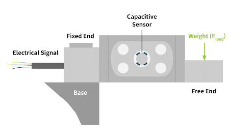
Fig 10. Capacitive Load Cell Diagram
Capacitive Load Cell's internal parts
The internal parts of a capacitive load cell typically include the following components:
- Capacitive Plates: Capacitive load cells consist of two or more conductive plates. These plates are typically made of metal, such as stainless steel or aluminum. One plate is fixed or connected to the load cell housing, while the other plate(s) are subjected to the applied force. The distance between the plates determines the capacitance.
- Deformation Element: The deformation element, also known as the flexure, is part of the load cell that experiences mechanical deformation when a force is applied. It connects the movable plate(s) to the load cell body. The deformation element is designed to provide flexibility while maintaining structural integrity.
- Insulating Material: Insulating materials, such as non-conductive polymers or ceramics, are used to separate the conductive plates and prevent electrical short circuits. These insulating materials ensure that the capacitance is primarily influenced by the applied force and not affected by the surrounding environment.
- Electrical Circuitry: Capacitive load cells have an electrical circuit that connects to the plates. The circuit applies an electrical voltage or charge to the plates, creating an electric field between them. The circuit also measures the capacitance changes and converts them into an electrical signal for further processing.
- Signal Conditioning Electronics: Capacitive load cells require signal conditioning electronics to process the capacitance change into a measurable force signal. This may include amplification, filtering, and calibration circuitry to ensure accurate and reliable force measurements.
- Electrical Leads: Electrical leads or cables connect the load cell to external measurement devices or control systems. These leads transmit the electrical signals from the load cell to the instrumentation for display, recording, or further analysis.
- Protective Enclosure: Capacitive load cells are often housed within a protective enclosure made of materials such as stainless steel or aluminum. The enclosure provides mechanical protection to the internal components and helps shield the load cell from environmental influences such as moisture, dust, and electromagnetic interference.
These internal components work together to measure the applied force and convert it into an electrical signal that can be used for force measurement and control purposes. The design and arrangement of these components may vary depending on the specific manufacturer and load cell model.
Capacitive Load Cells Types
There are different types of capacitive load cells based on their design and construction. Some common types include
- Parallel Plate Capacitive Load Cells: In this type, the load cell consists of two parallel plates separated by a small gap. The applied force causes deformation in the plates, resulting in a change in the capacitance between them.
- Diaphragm Capacitive Load Cells: Diaphragm capacitive load cells use a flexible diaphragm as the deformation element. The diaphragm bends or flexes under the applied force, changing the distance between the plates and thus altering the capacitance.
- Button Capacitive Load Cells: Button load cells have a cylindrical or button-like shape. They consist of a central diaphragm surrounded by concentric rings or segments. The applied force deforms the central diaphragm, causing changes in capacitance between the central diaphragm and the surrounding segments.
- Annular Capacitive Load Cells: Annular load cells have a ring-shaped structure with a central hole. They feature an inner and outer ring separated by a gap. The applied force deforms the structure, changing the capacitance between the inner and outer rings.
- Belleville Spring Capacitive Load Cells: Belleville spring load cells use a stack of conical Belleville springs as the deformation element. The compression or deflection of the Belleville springs under the applied force changes the capacitance between the plates.
These are just a few examples of the types of capacitive load cells available. The specific design and construction of capacitive load cells can vary based on factors such as load capacity, sensitivity, application requirements, and manufacturer preferences. Each type is suited for different force measurement applications and offers varying advantages in terms of accuracy, size, and performance.
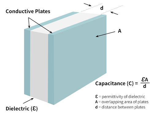
Fig 11. Capacitive Sensor within Capacitive Load Cell
What are Piezoelectric Load Cells?
Piezoelectric load cells are a type of load cell that utilizes the piezoelectric effect to measure applied forces. The piezoelectric effect is the ability of certain materials to generate an electrical charge in response to mechanical stress or pressure. In a piezoelectric load cell, this effect is harnessed to convert the applied force into an electrical signal.
The basic structure of a piezoelectric load cell consists of a piezoelectric material, typically a crystal or ceramic, which is bonded or attached to a mechanical element. When a force is applied to the load cell, the mechanical element deforms, causing stress or compression on the piezoelectric material. This deformation leads to the generation of an electrical charge across the material.
The generated electrical charge is proportional to the magnitude of the applied force, allowing the load cell to measure the force accurately. The electrical charge is typically very small and requires amplification and conditioning for further processing and measurement.
Piezoelectric load cells find applications in various industries, including aerospace, automotive, robotics, materials testing, and biomedical research, where precise force measurement and dynamic response are required.
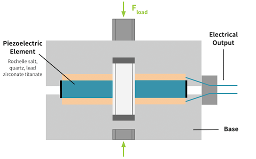
Fig 12. Piezoelectric Load Cell Diagram
How is the Piezoelectric Load Cell structure?
The structure of a piezoelectric load cell typically consists of the following components:
- Piezoelectric Element: The core component of a piezoelectric load cell is the piezoelectric element, which is typically a crystal or ceramic material. The piezoelectric material is chosen for its ability to generate an electrical charge when subjected to mechanical stress or pressure. Common materials used include quartz, lead zirconate titanate (PZT), and polyvinylidene fluoride (PVDF).
- Mechanical Element: The mechanical element of a piezoelectric load cell is responsible for transferring the applied force to the piezoelectric material. It can take different forms depending on the load cell design, such as a diaphragm, beam, or cantilever. The mechanical element undergoes deformation or displacement when the load is applied, exerting stress or compression on the piezoelectric material.
- Mounting Structure: The mounting structure holds the piezoelectric element and the mechanical element in place. It provides stability and ensures proper alignment for accurate force measurement. The mounting structure is typically made of a rigid material, such as metal or plastic.
- Electrical Leads: Electrical leads or cables are used to connect the piezoelectric element to the external measurement or control system. These leads transmit the generated electrical charge to the signal-conditioning circuitry for further processing.
- Signal Conditioning Electronics: Piezoelectric load cells require signal conditioning electronics to amplify, filter, and process the small electrical charge generated by the piezoelectric element. The signal conditioning circuitry converts the charge into a measurable voltage or current signal that can be used for force measurement or control purposes.
- Protective Enclosure: Piezoelectric load cells are often housed within a protective enclosure to shield internal components from environmental factors such as moisture, dust, and electromagnetic interference. The enclosure is typically made of materials such as stainless steel or aluminum.
The specific design and arrangement of these components may vary depending on the manufacturer and load cell model. Some load cells may also include additional features such as temperature sensors for compensation purposes or integrated electronics for signal conditioning and digital output.
Overall, the structure of a piezoelectric load cell is designed to convert the applied force into an electrical charge through the piezoelectric effect and provide a reliable and accurate measurement of the force.
Piezoelectric Load Cells Working Principle
The working principle of a piezoelectric load cell is based on the piezoelectric effect, which is the ability of certain materials to generate an electrical charge in response to mechanical stress or pressure. In a piezoelectric load cell, this effect is utilized to convert the applied force into an electrical signal for force measurement.
The working principle can be summarized in the following steps:
- Applied Force: When a force is applied to a piezoelectric load cell, the mechanical element (such as a diaphragm or beam) undergoes deformation or displacement. This deformation creates stress or compression on the piezoelectric material.
- Piezoelectric Effect: The applied stress or compression on the piezoelectric material causes a rearrangement of the material's internal charge distribution. This generates an electrical charge across the material.
- Charge Generation: The generated electrical charge is proportional to the magnitude of the applied force. The charge distribution occurs within the crystal lattice structure of the piezoelectric material.
- Electrical Signal: The generated electrical charge is collected by the electrodes on the surface of the piezoelectric material. These electrodes are connected to the load cell's electrical leads or cables.
- Signal Conditioning: The collected electrical charge is very small and requires amplification and conditioning for further processing and measurement. The electrical signal is typically converted into a measurable voltage or current signal through signal conditioning electronics.
- Force Measurement: The amplified electrical signal is then used to determine the magnitude of the applied force. It can be calibrated and converted into a force measurement reading using appropriate calibration techniques.
It's important to note that the piezoelectric effect is reversible, meaning that the piezoelectric material can also deform in response to an applied electrical voltage. This property allows piezoelectric load cells to be used not only for force measurement but also for force control or actuation applications.
By harnessing the piezoelectric effect, piezoelectric load cells provide a reliable and accurate means of measuring forces in a wide range of applications. Their high sensitivity, fast response time, and ability to measure dynamic forces make them suitable for various industries, including aerospace, automotive, manufacturing, and research fields.
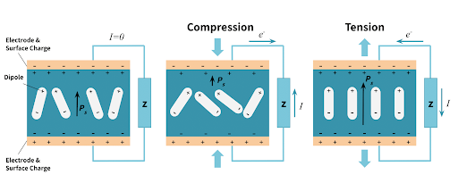
Fig 13. Piezoelectric Effect within Piezoelectric Element in Tension and Compression
All Types of Piezoelectric Load Cells
There are several types of piezoelectric load cells, each designed to suit specific force measurement applications. Here are some common types of piezoelectric load cells:
- Shear Mode Piezoelectric Load Cell: In a shear mode load cell, the piezoelectric material is oriented in a shear configuration. The applied force causes shear deformation in the material, generating an electrical charge. These load cells are compact, have a low profile, and offer high sensitivity.
- Compression Mode Piezoelectric Load Cell: Compression mode load cells are designed to measure forces that act in a compressive direction. The piezoelectric material is subjected to compression, resulting in the generation of an electrical charge. These load cells are suitable for applications where forces are applied in a straight-line compression direction.
- Ring-type Piezoelectric Load Cell: Ring-type load cells consist of a circular or annular piezoelectric element. The force is applied to the inner or outer circumference of the ring, causing the piezoelectric material to deform and generate an electrical charge. These load cells are often used in applications where the force needs to be applied circularly or radially.
- Bending Mode Piezoelectric Load Cell: Bending mode load cells utilize the bending deformation of a piezoelectric element to measure forces. The applied force causes the piezoelectric material to bend, leading to the generation of an electrical charge. These load cells are suitable for applications where the force is applied in a bending or flexing manner.
- Pancake-type Piezoelectric Load Cell: Pancake-type load cells have a flat, disc-like shape and are designed to measure forces applied in a planar direction. They offer high stiffness and are commonly used in applications that require the measurement of forces acting in a horizontal plane, such as material testing or force control in robotic applications.
- Multi-Axis Piezoelectric Load Cell: Multi-axis load cells incorporate multiple piezoelectric elements to measure forces in different directions simultaneously. They can measure forces in multiple axes or directions, such as compression, tension, and shear forces, providing comprehensive force measurement capabilities.
These are just a few examples of the types of piezoelectric load cells available. Each type offers specific advantages and is suitable for different force measurement requirements. The selection of the appropriate load cell type depends on factors such as the direction and magnitude of the force, environmental conditions, and the desired sensitivity and accuracy of the measurement.
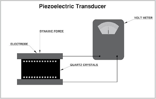
Fig 14. Piezoelectric load cells
What are the Magnetic Load Cells?
Magnetic load cells, also known as magnetoresistive load cells or magnetic force sensors, are a type of load cell that uses the principles of magnetoresistance to measure forces. These load cells utilize the changes in magnetic fields caused by applied forces to generate an electrical output that is proportional to the force being measured.
The basic structure of a magnetic load cell typically consists of the following components:
- Permanent Magnets: Magnetic load cells contain permanent magnets that create a magnetic field within the load cell assembly. These magnets establish a reference magnetic field that is affected by the presence of an applied force.
- Ferromagnetic Material: The load-bearing element of a magnetic load cell is made of a ferromagnetic material that interacts with the magnetic field. This material exhibits changes in magnetic properties, such as resistance or permeability, in response to applied forces.
- Sensor Element: The sensor element within the magnetic load cell detects the changes in the magnetic field caused by the applied force. It can be a magnetoresistive sensor, such as a giant magnetoresistive (GMR) or an anisotropic magnetoresistive (AMR) sensor, or a magnetic induction sensor.
- Signal Conditioning Electronics: The electrical output from the sensor element is processed by signal conditioning electronics. These electronics amplify, filter, and convert the sensor's output into a measurable signal that can be used for force measurement or control.
Magnetic Load Cells internal parts
Magnetic load cells, also known as magnetoresistive load cells or magnetic force sensors, typically consist of the following internal parts:
- Load-Bearing Element: The load-bearing element is part of the load cell that directly experiences the applied force. It can be a mechanical structure, such as a plate or beam, that deforms or experiences changes in its magnetic properties when subjected to force. The load-bearing element is usually made of a ferromagnetic material that interacts with the magnetic field.
- Permanent Magnets: Magnetic load cells incorporate permanent magnets within their structure. These magnets establish a reference magnetic field within the load cell assembly. The magnets are strategically positioned to interact with the load-bearing element and are designed to create a stable and uniform magnetic field.
- Sensor Element: The sensor element is responsible for detecting the changes in the magnetic field caused by the applied force. It can be a magnetoresistive sensor or a magnetic induction sensor. Magnetoresistive sensors, such as giant magnetoresistive (GMR) or anisotropic magnetoresistive (AMR) sensors, are commonly used in magnetic load cells. These sensors exhibit changes in electrical resistance proportional to the magnetic field variations. Magnetic induction sensors utilize changes in magnetic flux to generate an electrical output signal.
- Signal Conditioning Electronics: The electrical output from the sensor element is processed by signal conditioning electronics. These electronics amplify, filter, and convert the sensor's output into a measurable signal that corresponds to the applied force. Signal conditioning electronics may include amplifiers, filters, analog-to-digital converters (ADCs), and other components to ensure accurate and reliable force measurement.
- Output Interface: Magnetic load cells often feature an output interface to transmit the measured force data to external devices or systems. The output interface can be in the form of analog voltage or current signals, digital signals (such as RS-232, USB, or Ethernet), or wireless communication protocols, depending on the specific load cell design and application requirements.
The internal parts of magnetic load cells work together to detect and measure the changes in the magnetic field caused by the applied force. This allows for the conversion of the force into an electrical signal that can be utilized for force measurement, control, or monitoring purposes.
How do Magnetic Load Cells run?
Magnetic load cells operate based on the principles of magnetoresistance or magnetic induction. The exact working mechanism may vary depending on the specific design and technology employed in the load cell. Here's a general overview of how magnetic load cells run:
- Magnetic Field Establishment: Magnetic load cells incorporate permanent magnets within their structure. These magnets create a stable and uniform magnetic field within the load cell assembly. The magnetic field serves as a reference for measuring the applied force.
- Load Application: When a force is applied to the load-bearing element of the load cell, it undergoes deformation or experiences changes in its magnetic properties. This change in the load-bearing element alters the magnetic field within the load cell.
- Magnetic Field Variation Detection: The sensor element within the load cell detects the changes in the magnetic field caused by the applied force. The specific type of sensor element used depends on the load cell's design, such as a magnetoresistive sensor or a magnetic induction sensor.
- Magnetortive Sensor: If a magnetoresistive sensor, such as a giant magnetoresistive (GMR) or anisotropic magnetoresistive (AMR) sensor, is used, it exhibits changes in electrical resistance in response to variations in the magnetic field. These changes in resistance are proportional to the applied force.
- Magnetic Induction Sensor: In the case of a magnetic induction sensor, variations in the magnetic field induced changes in the magnetic flux. This change in flux generates an electrical output signal proportional to the applied force.
- Electrical Signal Conversion: The electrical output signal from the sensor element is passed through signal conditioning electronics. These electronics amplify, filter, and convert the signal into a measurable form that corresponds to the applied force. The signal conditioning electronics may also include calibration and compensation techniques to ensure accurate force measurements.
- Force Measurement: The converted electrical signal represents the measured force. It can be provided as an analog voltage or current signal or converted to a digital form for further processing or transmission to external devices or systems.
By detecting and quantifying the changes in the magnetic field caused by the applied force, magnetic load cells provide a means to measure forces accurately. The exact operational details may vary depending on the specific load cell technology used, but the basic principle involves the interaction between the applied force, magnetic field variations, and the sensor element to generate an electrical output proportional to the force being measured.
Magnetic Load Cells Types
There are different types of magnetic load cells available, each with its own design and working principles. Here are some common types of magnetic load cells:
- Magnetoresistive Load Cells: These load cells utilize magnetoresistive sensors, such as giant magnetoresistive (GMR) or anisotropic magnetoresistive (AMR) sensors, to measure forces based on changes in electrical resistance caused by variations in the magnetic field.
- Hall Effect Load Cells: Hall effect load cells use Hall effect sensors to detect changes in the magnetic field and convert them into electrical signals. Hall effect sensors rely on the Hall effect phenomenon, where a voltage is generated across a conductor when it is exposed to a magnetic field.
- Magnetic Induction Load Cells: Magnetic induction load cells work based on the principle of magnetic induction. Changes in the magnetic field induced changes in magnetic flux, which are detected by the sensor element and converted into electrical signals.
- Fluxgate Load Cells: Fluxgate load cells utilize a fluxgate magnetometer, which consists of a ferromagnetic core and a coil, to measure changes in the magnetic field caused by applied forces. The fluxgate magnetometer detects changes in the magnetic flux and converts them into electrical signals.
- Magnetostrictive Load Cells: Magnetostrictive load cells rely on the magnetostrictive effect, where certain materials change their dimensions in response to a magnetic field. The deformation of the magnetostrictive material is measured and used to determine the applied force.
These are some of the common types of magnetic load cells, each with its working principle and design. The choice of load cell type depends on the specific application requirements, accuracy needs, environmental conditions, and other factors.
References
https://realpars.com/load-cell/
https://instrumentationandcontrollers.blogspot.com/2010/11/load-cell-and-load-cell-types.html
https://www.iqsdirectory.com/articles/load-cell.html
Recent Posts
-

Booster Pump Troubleshooting and Maintenance: How to Fix and Prevent Common Issues
1. Introduction Imagine turning on your faucet only to be greeted with a weak trickle of water when …22nd Apr 2025 -

Energy-Efficient Booster Pumps: Selection and Tips for Maximizing Performance
1. Introduction Imagine never having to deal with fluctuating water pressure, noisy pumps, or skyroc …19th Apr 2025 -

Booster Pumps for Sustainable Water Systems: Irrigation and Rainwater Harvesting Solutions
1. Introduction Water scarcity is no longer a distant threat—it’s a reality affecting millions …16th Apr 2025