

Transforming Noise into Knowledge: The Art of Signal Conditioning
Signal conditioning circuitry is the unsung hero of modern electronics, silently working behind the scenes to transform raw sensor data into meaningful information. Like a skilled conductor shaping a cacophonous orchestra into harmonious music, signal conditioning harmonizes electrical signals, ensuring they are accurate, reliable, and fit for their intended purpose.
In the world of technology and measurement, where sensors are the eyes and ears of machines, signal conditioning is the brain that interprets their language. It takes the often faint, noisy, or raw electrical signals produced by sensors and transducers and turns them into refined, precise, and actionable data. This transformation is the secret sauce that underpins the accuracy and reliability of countless electronic systems across industries as diverse as manufacturing, healthcare, aerospace, and environmental monitoring.
In this digital age, where sensors and electronic devices surround us, understanding the role of signal conditioning is essential. From amplifying weak signals to filtering out interference, from scaling voltages to compensating for temperature variations, signal conditioning circuitry is the cornerstone of data accuracy, enabling us to navigate a world where information is power. Let's dive deeper into the world of signal conditioning to uncover its mysteries and significance.
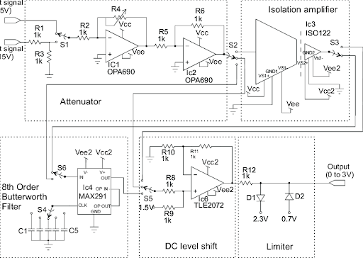
Fig 1. Schematic diagram of the signal conditioning circuit.
Signal Conditioning Circuitry
Signal conditioning circuitry refers to the set of electronic components and techniques used to manipulate and prepare an input signal for processing or measurement in electronic systems. The goal of signal conditioning is to enhance the accuracy, reliability, and compatibility of the signal with the rest of the system. Signal conditioning is commonly used in various applications, including data acquisition, instrumentation, communication systems, and control systems.
Key functions of signal conditioning circuitry include
- Amplification: Signals from sensors or transducers often have very low amplitudes and may need to be amplified to a level suitable for further processing. Operational amplifiers (op-amps) are commonly used for this purpose.
- Filtering: Unwanted noise, interference, or high-frequency components in a signal can degrade the quality of the measurement or communication. Filters, such as low-pass, high-pass, band-pass, and notch filters, are used to remove or attenuate unwanted frequency components.
- Offset Adjustment: Sometimes, it's necessary to shift the DC level (offset) of a signal. This can be achieved using DC biasing or level-shifting circuits.
- Signal Isolation: In some applications, it's crucial to electrically isolate the input signal from the rest of the circuit to prevent ground loops or protect sensitive equipment. Isolation techniques can include transformers, optocouplers, or isolation amplifiers.
- Voltage Regulation: Ensuring a stable power supply voltage is essential for maintaining signal integrity. Voltage regulators are used to provide a constant output voltage, reducing the impact of power supply variations.
- Linearization: Some sensors produce nonlinear output signals, which can be converted into a linear response through signal conditioning techniques. For instance, a thermistor's resistance-temperature curve can be linearized.
- Signal Conversion: Signal conditioning may also involve converting one type of signal into another. For example, analog-to-digital converters (ADCs) are used to convert analog signals into digital data for processing by microcontrollers or computers.
- Impedance Matching: To optimize power transfer between two components (e.g., sensors and amplifiers), impedance matching circuits may be employed.
- Signal Rectification and Scaling: Depending on the application, signal conditioning may involve rectifying AC signals to obtain their absolute value and scaling them to match the desired measurement range.
- Signal Conditioning for Communication: In communication systems, signal conditioning circuits may include modulation, demodulation, and encoding/decoding functions to prepare data for transmission and reception.
Signal conditioning circuitry can be customized to suit the specific requirements of a given application. The choice of components and techniques depends on factors such as the nature of the input signal, the desired output, noise considerations, and the overall system design. Proper signal conditioning is critical for accurate and reliable data acquisition, control, and communication in electronic systems.
Signal Conditioning Circuitry in pressure transmitters
Signal conditioning circuitry plays a crucial role in pressure transmitters, which are devices used to measure and transmit pressure information from various industrial processes. Pressure transmitters typically involve the conversion of physical pressure into an electrical signal, which needs to be conditioned to ensure accuracy, reliability, and compatibility with control systems or data acquisition equipment. Here's how signal conditioning is applied in pressure transmitters:
- Pressure Sensing Element: Pressure transmitters typically contain a pressure sensing element (e.g., strain gauge, capacitive sensor, piezoelectric crystal) that undergoes physical changes in response to pressure variations.
- Bridge Circuit: Many pressure sensors, especially strain gauge-based ones, are integrated into a Wheatstone bridge circuit. The bridge output voltage varies with applied pressure, but it may be small and require amplification.
- Amplification: Signal conditioning often begins with amplification to increase the level of the sensor's output signal. Operational amplifiers (op-amps) are commonly used for this purpose. The gain of the amplifier can be adjusted to match the sensor's sensitivity and the desired output range.
- Offset Adjustment: Pressure transmitters may include offset adjustment to set the output to a specific value when there is no pressure applied. This is often done using potentiometers or digital calibration techniques.
- Filtering: Pressure measurements can be sensitive to noise and high-frequency variations. Low-pass filters are employed to remove unwanted noise components while preserving the integrity of the pressure signal.
- Linearization: Some pressure sensors exhibit nonlinear behavior, particularly at extreme pressure ranges. Signal conditioning may include linearization techniques to ensure that the output signal is linearly proportional to the pressure input over the desired range.
- Temperature Compensation: Pressure transmitters often incorporate temperature compensation to correct for variations in sensor performance due to temperature changes. This is especially important in industrial applications where temperature fluctuations can be significant.
- Digital Conversion: In modern pressure transmitters, the analog output from the signal conditioning circuitry is often converted into a digital signal using analog-to-digital converters (ADCs). This digitized data can be more easily processed and transmitted to control systems or data acquisition equipment.
- Communication Interface: The conditioned and digitized pressure signal can be transmitted via various communication interfaces, such as analog outputs (e.g., 4-20 mA), digital protocols (e.g., HART, Modbus), or even wireless communication, depending on the application requirements.
- Power Supply Regulation: To ensure stable performance, pressure transmitters may include voltage regulation circuitry to maintain a consistent power supply voltage for the signal conditioning components.
- Diagnostic and Calibration Features: Some advanced pressure transmitters include diagnostic features to monitor sensor health, detect faults, and trigger calibration routines as needed. This enhances reliability and minimizes downtime in industrial processes.
In summary, signal conditioning circuitry in pressure transmitters is essential for converting the raw pressure sensor data into a reliable and accurate electrical signal that can be easily processed and transmitted. The specific signal conditioning techniques and components used can vary based on the type of pressure sensor, the required accuracy, and the demands of the application.
How many parts does a Signal Conditioning Circuitry consist of?
The number of components or parts in a signal conditioning circuitry can vary widely depending on the complexity of the circuit and its specific application. Signal conditioning circuits can range from simple circuits with just a few components to more complex designs with multiple components. Here are some of the common components you might find in a signal conditioning circuit:
- Sensor or Transducer: This is the primary component that generates the electrical signal in response to a physical phenomenon (e.g., pressure, temperature, light, etc.).
- Bridge Circuit (if applicable): In some cases, particularly with strain gauge-based sensors, a Wheatstone bridge circuit may be part of the sensor assembly.
- Amplifier (Operational Amplifier - Op-Amp): Often, a signal conditioner includes one or more operational amplifiers for amplifying the sensor's output signal.
- Resistors: Resistors are used for setting the gain of amplifiers, creating voltage dividers, and adjusting offsets.
- Capacitors: Capacitors can be used for coupling, filtering, and timing purposes in the circuit.
- Inductors: Inductors are used in certain filter designs, particularly in high-frequency applications.
- Diodes and Rectifiers: Diodes may be used for signal rectification and protection.
- Transistors: Transistors can be used for signal switching and amplification in certain circuit configurations.
- Filters: Passive and active filters may be included to shape the frequency response of the circuit.
- Digital Components: In some cases, digital components like microcontrollers, analog-to-digital converters (ADCs), and digital-to-analog converters (DACs) may be part of the signal conditioning circuitry.
- Voltage Regulators: Voltage regulators ensure a stable power supply voltage for the circuit.
- Isolation Components: If electrical isolation is required, components like optocouplers, transformers, or isolation amplifiers may be included.
- Calibration Components: Potentiometers or digital calibration circuits may be used to fine-tune the circuit's performance.
- Communication Interfaces: Components for communication, such as transceivers or modems, might be included in advanced signal conditioning circuits.
- Protection Components: Circuitry for overvoltage protection, reverse voltage protection, and other safety features may be added to safeguard the components.
- Temperature Compensation Components: In applications where temperature affects the signal, temperature compensation components like thermistors or resistors may be used.
- Diagnostic and Monitoring Components: For advanced applications, diagnostic features like sensors for monitoring circuit health and performance may be included.
The number and type of components in a signal conditioning circuit depend on the specific requirements of the application, the desired signal conditioning functions, and the complexity of the circuit design. Simple circuits may consist of just a sensor and an amplifier, while more complex circuits may involve several of the components listed above to meet the desired performance specifications and functionality.
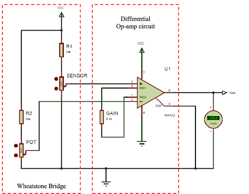
Fig 2. Schematic diagram of the signal conditioning circuit
How is a Signal Conditioning Circuitry structure?
A signal conditioning circuitry's structure can vary depending on the specific application and the functions it needs to perform. However, there is a general structure that can be followed as a guideline for designing signal conditioning circuits. Here's a typical structure for a signal conditioning circuit:
- Input Stage:
- Sensor or Transducer: This is the starting point of the signal conditioning circuit. It converts a physical quantity (e.g., temperature, pressure, voltage) into an electrical signal.
- Sensor Interface: This may include any necessary components to interface the sensor with the circuit, such as biasing networks or voltage dividers.
- Amplification Stage:
- Amplifier (Op-Amp): Typically, an operational amplifier is used to amplify the low-level signal from the sensor. The gain of the amplifier can be adjusted to match the sensor's output and the desired output range.
- Filtering Stage:
- Filter(s): Filters are used to remove unwanted noise and high-frequency components from the signal. Common filter types include low-pass, high-pass, band-pass, and notch filters.
- Linearization Stage (if needed):
- Linearization Circuitry: Some sensors exhibit nonlinear behavior, and additional circuitry may be needed to linearize the signal, ensuring a linear relationship between the input and output.
- Offset and Calibration Stage (if needed):
- Offset Adjustment: This stage allows for setting the output to a specific value when there is no input signal (offset calibration).
- Calibration Components: Potentiometers or digital calibration circuits may be used to calibrate and fine-tune the circuit's performance.
- Temperature Compensation Stage (if needed):
- Temperature Compensation Circuitry: In applications where temperature affects the signal, compensation components like thermistors or resistors may be included.
- Output Stage:
- Signal Conversion (if needed): In some cases, the analog signal may be converted into a digital signal using analog-to-digital converters (ADCs) or digital-to-analog converters (DACs).
- Output Interface: This stage includes components or circuits for interfacing with the external system, such as voltage output, current output (e.g., 4-20 mA), or digital communication interfaces (e.g., HART, Modbus).
- Power Supply Regulation Stage:
- Voltage Regulator: To ensure stable performance, voltage regulators are often included to maintain a consistent power supply voltage for the circuit.
- Isolation and Protection Stage (if needed):
- Isolation Components: If electrical isolation is required, components like optocouplers, transformers, or isolation amplifiers may be included.
- Protection Components: Circuitry for overvoltage protection, reverse voltage protection, and other safety features may be added to safeguard the components.
- Diagnostic and Monitoring Stage (if needed):
- Diagnostic Features: For advanced applications, diagnostic features like sensors for monitoring circuit health and performance may be included.
- Grounding and Shielding (if needed):
- Grounding: Proper grounding is essential to minimize noise and ensure accurate signal conditioning.
- Shielding: In electrically noisy environments, shielding may be added to protect the circuit from external interference.
- Power Supply:
- Power Source: The circuit requires a stable power source to operate, which can be provided by batteries, an external power supply, or other sources.
The specific components and stages in a signal conditioning circuit will depend on the application's requirements and the characteristics of the input signal. Engineers and designers tailor the structure and components to achieve the desired performance, accuracy, and reliability for the specific task the circuit is intended to perform.
What are the components of a signal conditioning circuit?
Signal conditioning circuits consist of various components that work together to prepare, process, and enhance an input signal. The specific components used in a signal conditioning circuit can vary depending on the application, but here is a list of common components that you might find in such circuits:
- Sensor or Transducer: This is the device that converts a physical quantity (e.g., pressure, temperature, light) into an electrical signal.
- Amplifier: Operational amplifiers (op-amps) are frequently used to amplify the input signal, making it stronger and more suitable for further processing.
- Resistors: Resistors are used for various purposes, including setting the gain of amplifiers, creating voltage dividers, and adjusting offset voltages.
- Capacitors: Capacitors are used for coupling, filtering, and timing applications within the circuit.
- Inductors: Inductors are used in certain filter designs, particularly in high-frequency applications.
- Diodes and Rectifiers: Diodes may be used for signal rectification and protection against reverse voltage.
- Transistors: Transistors can be used for signal switching and amplification in certain circuit configurations.
- Filters: Filters, both passive (e.g., RC filters) and active (e.g., Sallen-Key filters), can be employed to shape the frequency response of the circuit.
- Voltage Regulators: Voltage regulators maintain a stable power supply voltage for the circuit.
- Isolation Components: Components like transformers, optocouplers, or isolation amplifiers may be included to provide electrical isolation between parts of the circuit.
- Digital Components: In some cases, microcontrollers, analog-to-digital converters (ADCs), and digital-to-analog converters (DACs) are used for signal processing and digital communication.
- Calibration Components: Potentiometers or digital calibration circuits may be used for fine-tuning and calibration of the circuit.
- Communication Interfaces: In modern systems, communication interfaces like UART, SPI, I2C, HART, or Modbus may be integrated for transmitting data to external devices or systems.
- Protection Components: Circuitry for overvoltage protection, reverse voltage protection, and other safety features can safeguard the components.
- Diagnostic and Monitoring Components: For advanced applications, diagnostic features like sensors for monitoring circuit health, detecting faults, and triggering calibration routines may be included.
- Grounding and Shielding: Proper grounding and shielding techniques are essential to minimize noise and ensure accurate signal conditioning, especially in electrically noisy environments.
- Power Supply: A stable power supply is required to operate the circuit. Power sources may include batteries, external power supplies, or other sources.
The choice of components and their arrangement in a signal conditioning circuit depends on the nature of the input signal, the desired output, noise considerations, and the overall system design. Engineers and designers select and configure these components to achieve the desired signal conditioning and processing objectives for a specific application.
How does Signal Conditioning Circuitry work?
Signal conditioning circuitry works by taking a raw, often weak, and possibly noisy input signal and processing it to produce an output signal that is more suitable for further processing, measurement, or communication. The goal is to enhance the signal's accuracy, reliability, and compatibility with the rest of the electronic system. Here's a general overview of how signal conditioning circuitry works:
- Input Signal Acquisition:
- The signal conditioning process begins by acquiring an input signal from a sensor or transducer. This input signal can be in the form of voltage, current, resistance, or any other electrical parameter that represents a physical quantity (e.g., temperature, pressure, light intensity).
- Amplification:
- Often, the input signal from the sensor is weak and needs to be amplified to a level suitable for further processing. Operational amplifiers (op-amps) are commonly used for amplification. The gain of the amplifier can be adjusted to match the sensor's sensitivity and the desired output range.
- Filtering:
- Unwanted noise, interference, or high-frequency components may be present in the input signal. Filtering is employed to remove or attenuate these unwanted frequency components. Different types of filters, such as low-pass, high-pass, band-pass, and notch filters, can be used based on specific requirements.
- Linearization (if needed):
- Some sensors produce nonlinear output signals. Signal conditioning may include linearization techniques to ensure that the output signal is linearly proportional to the physical quantity being measured.
- Offset and Calibration (if needed):
- Offset adjustment allows for setting the output to a specific value when there is no input signal. Calibration components like potentiometers or digital calibration circuits may be used to fine-tune the circuit's performance and accuracy.
- Temperature Compensation (if needed):
- In applications where temperature affects the sensor's output, compensation circuitry is included to correct for variations in sensor performance due to temperature changes.
- Signal Conversion (if needed):
- In modern systems, the analog output from the signal conditioning circuitry is often converted into a digital signal using analog-to-digital converters (ADCs). This digitized data can be more easily processed by microcontrollers or computers.
- Output Generation:
- The conditioned signal is then provided as the output of the signal-conditioning circuit. This output can be in various forms, such as analog voltage, current, or digital data, depending on the application and the interface requirements.
- Isolation and Protection (if needed):
- In some cases, electrical isolation is necessary to prevent ground loops or protect sensitive equipment. Isolation components like optocouplers, transformers, or isolation amplifiers may be included. Protection components can safeguard the circuit from overvoltage, reverse voltage, and other potential risks.
- Diagnostic and Monitoring (if needed):
- For advanced applications, diagnostic features may be included to monitor circuit health, detect faults, and trigger calibration routines as needed. This enhances reliability and minimizes downtime.
- Grounding and Shielding (if needed):
- Proper grounding and shielding techniques are essential to minimize noise and ensure accurate signal conditioning, especially in electrically noisy environments.
- Power Supply:
- The signal conditioning circuit requires a stable power supply to operate, which can be provided by batteries, an external power source, or other means.
Overall, signal conditioning circuitry optimizes the input signal for the specific requirements of a given application, making it suitable for subsequent processing, measurement, or transmission within an electronic system. The design and components of the circuit are tailored to achieve the desired performance and functionality for the application at hand.
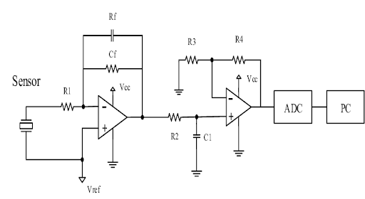
Fig 3. Schematic of signal conditioning circuit for piezoelectric sensor.
How many types does a Signal Conditioning Circuitry have?
Signal conditioning circuitry encompasses a wide range of techniques and components, and it can be customized for various applications. There are several types or categories of signal conditioning circuits, each designed to perform specific functions and tailored to the characteristics of the input signal and the requirements of the application. Here are some common types of signal conditioning circuitry:
- Amplification Circuits: These circuits are designed to increase the amplitude or gain of an input signal. Amplification is often necessary when the sensor's output is too weak for further processing.
- Filtering Circuits: Filtering circuits are used to remove unwanted noise, interference, or high-frequency components from an input signal. Common filter types include low-pass, high-pass, band-pass, and notch filters.
- Linearization Circuits: Some sensors produce nonlinear output signals. Linearization circuits are used to convert these nonlinear signals into linear responses, making them easier to interpret and work with.
- Voltage and Current Scaling Circuits: These circuits are used to scale voltage or current signals to match the desired measurement range or interface requirements of the receiving equipment.
- Offset Adjustment Circuits: Offset adjustment circuits allow for setting the output to a specific value when there is no input signal. This is often used to calibrate the circuit or to eliminate any DC offset in the signal.
- Temperature Compensation Circuits: In applications where temperature affects the sensor's output, compensation circuits are included to correct for temperature-induced variations in the signal.
- Signal Rectification and Conditioning: These circuits convert AC signals into DC signals, rectify signals to obtain their absolute values, or perform other operations to prepare the signal for further processing.
- Isolation Circuits: Isolation circuits are used to electrically isolate the input and output of the signal conditioning circuit to prevent ground loops and provide safety in high-voltage or noisy environments.
- Digital Signal Conditioning: In some applications, the signal may be digitized and processed digitally. Digital signal conditioning circuits involve analog-to-digital conversion (ADC) and digital signal processing (DSP) techniques.
- Communication and Interface Circuits: These circuits enable the conditioned signal to be transmitted to external devices or systems, using various communication protocols such as analog output (e.g., 4-20 mA), digital communication (e.g., UART, SPI, I2C), or wireless communication.
- Diagnostic and Monitoring Circuits: Advanced signal conditioning circuits may include diagnostic features such as sensors for monitoring circuit health, detecting faults, and triggering calibration routines.
- Bridge Circuitry: In some cases, signal conditioning involves bridge circuits, particularly in strain gauge-based sensors. These circuits are used to convert the small resistance changes in strain gauges into voltage or current signals.
- Calibration Circuits: Calibration circuits allow for adjusting and fine-tuning the performance of the signal conditioning circuit to achieve accurate measurements.
- Power Supply Regulation: Ensuring a stable power supply voltage is crucial for maintaining signal integrity. Voltage regulators and power conditioning circuits may be included for this purpose.
- Protection Circuits: These circuits safeguard the signal conditioning circuit from overvoltage, reverse voltage, and other potential risks.
The specific type of signal conditioning circuit used depends on the nature of the input signal, the requirements of the application, and the desired output. Engineers and designers select and design the appropriate type of signal conditioning circuitry to meet the unique needs of their systems.
How many types does Signal Conditioning Circuitry have in pressure measurements?
In pressure measurement applications, signal conditioning circuitry can vary depending on the specific type of pressure sensor or transducer used and the requirements of the measurement system. Signal conditioning is used to process and prepare the output of pressure sensors for accurate measurement and data acquisition. Here are some common types of signal conditioning circuitry used in pressure measurement:
- Bridge Circuitry: Many pressure sensors, especially those based on strain gauges, use Wheatstone bridge configurations. Signal conditioning may involve bridge completion and balancing circuits to maximize sensitivity and accuracy.
- Voltage Scaling: Some pressure sensors provide a voltage output that may need to be scaled to match the desired measurement range or interface requirements.
- Current Scaling (4-20 mA Loop): In industrial applications, a common output signal format for pressure transmitters is a 4-20 mA current loop. Signal conditioning is used to generate and scale this current signal.
- Offset Adjustment: Offset adjustment circuits allow for setting the output to a specific value when there is no pressure applied, which is often used for calibration purposes.
- Temperature Compensation: Pressure measurements can be temperature-sensitive. Temperature compensation circuits are correct for variations in sensor performance due to temperature changes.
- Filtering and Noise Reduction: Filtering circuits are employed to remove noise and unwanted high-frequency components from the pressure signal.
- Linearization: Some pressure sensors exhibit nonlinear behavior. Linearization circuits are used to ensure that the output signal is linearly proportional to the applied pressure.
- Output Interface: The conditioned signal can be provided in various forms, including analog voltage, current, or digital data, depending on the interface requirements of the measurement system.
- Signal Isolation: To prevent ground loops or ensure electrical safety, isolation circuits using optocouplers, transformers, or isolation amplifiers may be included.
- Communication Interfaces: In modern pressure measurement systems, signal conditioning may include communication interfaces like HART, Modbus, or others for transmitting data to control systems or data acquisition equipment.
- Diagnostic and Monitoring Features: Some advanced pressure measurement systems include diagnostic features to monitor sensor health, detect faults, and trigger calibration routines.
- Power Supply Regulation: Voltage regulators and power conditioning circuits ensure a stable power supply voltage for the signal conditioning components.
- Protection Circuits: Protection components safeguard the signal conditioning circuitry from overvoltage, reverse voltage, and other potential risks.
The specific type of signal conditioning circuitry used in pressure measurements depends on factors such as the type of pressure sensor, the measurement range, the required accuracy, and the environmental conditions of the application. Engineers select and design the appropriate signal conditioning circuitry to ensure accurate and reliable pressure measurements.
Amplification Circuitry:
Bridge Circuitry:
Voltage Scaling:
Current Scaling (4-20 mA Loop):
Offset Adjustment:
Temperature Compensation:
Comparing table
Certainly! Below is a comparison table that summarizes the different types of signal conditioning circuitry used in pressure measurements, including a brief description, operation, and typical applications for each type:
| Type of Signal Conditioning Circuitry | Description | Operation | Typical Applications |
| Amplification Circuitry | Amplifies weak pressure sensor signals | Uses operational amplifiers (op-amps) to provide gain | Industrial automation, aerospace, automotive |
| Bridge Circuitry | Converts mechanical strain to electrical signals | Utilizes the Wheatstone Bridge principle | Load cells, pressure transducers, force sensors |
| Voltage Scaling | Adjusts voltage output to match measurement range | Employs voltage dividers or amplifiers | Data acquisition, instrumentation, process control |
| Current Scaling (4-20 mA Loop) | Generates and scales a 4-20 mA current signal | Uses precision resistors and voltage-to-current conversion | Process control, PLC interfacing, industrial automation |
| Offset Adjustment | Sets output to a specific value at zero pressure | Adjusts offset using potentiometers or digital methods | Pressure transmitters, barometric sensors |
| Temperature Compensation | Corrects for temperature-induced variations in output | Uses compensation components based on ambient temperature | Weather stations, HVAC systems, tire pressure monitoring |
This table provides a concise overview of the different signal conditioning techniques, how they operate, and where they are commonly applied in pressure measurement systems. Keep in mind that the choice of signal conditioning circuitry depends on the specific sensor technology, measurement requirements, and environmental conditions of the application.
What is the purpose of using Signal Conditioning Circuitry?
The purpose of using signal conditioning circuitry is to prepare and enhance an input signal to make it suitable for further processing, measurement, or communication within an electronic system. Signal conditioning serves several important functions and provides various benefits in electronic applications. Here are the primary purposes and advantages of using signal conditioning circuitry:
- Amplification: Signal conditioning amplifies weak or low-level input signals, making them stronger and more easily detectable by downstream components. This is crucial for improving signal-to-noise ratios and ensuring accurate measurements.
- Filtering: Filtering is used to remove unwanted noise, interference, or high-frequency components from the signal. It helps clean up the signal and enhances its quality, especially in noisy environments.
- Linearization: In some cases, sensors may produce nonlinear output signals. Signal conditioning can include linearization techniques to ensure that the output signal is linearly proportional to the physical quantity being measured, simplifying data interpretation.
- Offset Adjustment: Offset adjustment allows for setting the output to a specific value when there is no input signal, helping to calibrate the system and eliminate DC offset.
- Voltage/Current Scaling: Signal conditioning can scale the signal to match the desired measurement range or interface requirements, making it compatible with the receiving equipment.
- Temperature Compensation: Temperature compensation circuitry corrects for variations in sensor performance due to temperature changes, ensuring accurate measurements over a wide temperature range.
- Signal Rectification: Signal rectification circuits convert AC signals into DC signals or rectify signals to obtain their absolute values. This is valuable in applications like demodulation and power measurement.
- Signal Conversion: In some cases, signal conditioning involves converting analog signals into digital data for processing by microcontrollers, computers, or digital systems.
- Isolation: Electrical isolation is used to prevent ground loops, enhance safety, and protect sensitive equipment by providing a barrier between input and output circuits.
- Diagnostic and Monitoring: Advanced signal conditioning circuits may include diagnostic features to monitor circuit health, detect faults, and trigger calibration routines, which improves reliability and minimizes downtime.
- Communication Interface: Signal conditioning may include communication interfaces (e.g., UART, SPI, I2C, HART) for transmitting data to external devices or systems.
- Protection: Signal conditioning can include components and circuits to safeguard against overvoltage, reverse voltage, and other potential risks.
The specific purpose and benefits of signal conditioning depend on the application and the nature of the input signal. Signal conditioning is widely used in various fields, including industrial automation, instrumentation, telecommunications, medical devices, and scientific research, to ensure accurate and reliable data acquisition, control, and communication within electronic systems.
What are the Signal Conditioning Circuitry applications?
Signal conditioning circuitry finds applications in a wide range of fields and industries where precise measurement, control, and communication of physical parameters are essential. These applications often involve sensors and transducers that convert physical phenomena into electrical signals, and signal conditioning is employed to process and enhance these signals. Here are some common applications of signal conditioning circuitry:
- Industrial Automation:
- Signal conditioning is used in manufacturing and process control systems to monitor variables like pressure, temperature, flow, and level. It ensures accurate data acquisition and control in industries such as chemical processing, food and beverage, and automotive manufacturing.
- Instrumentation:
- In scientific and laboratory instruments, signal conditioning enhances the accuracy and reliability of measurements. It is used in devices like oscilloscopes, spectrum analyzers, and data acquisition systems.
- Environmental Monitoring:
- Environmental sensors for weather stations, air quality monitoring, and soil analysis benefit from signal conditioning to process data and transmit it to monitoring stations.
- Medical Devices:
- Signal conditioning is critical in medical equipment like patient monitors, ECG machines, and blood pressure monitors to ensure accurate measurement of physiological parameters.
- Aerospace and Aviation:
- In aircraft and spacecraft, signal conditioning is used for monitoring various parameters such as altitude, airspeed, and engine performance. It aids in navigation, control, and communication systems.
- Automotive:
- Signal conditioning plays a role in automotive applications, including engine control units (ECUs), tire pressure monitoring systems (TPMS), and crash sensors.
- Telecommunications:
- In telecommunications equipment, signal conditioning circuits are used to improve the quality and reliability of signals, including those in optical fiber communications and cellular networks.
- Energy Management:
- Signal conditioning is used in power monitoring systems to measure parameters like voltage, current, and power factor. This data helps in optimizing energy consumption and grid management.
- Robotics:
- Robotics systems utilize signal conditioning for feedback control and sensors that provide information about joint positions, forces, and environmental conditions.
- HVAC and Building Automation:
- Heating, ventilation, and air conditioning (HVAC) systems, as well as building automation systems, use signal conditioning for temperature, humidity, and pressure sensors to maintain indoor comfort and energy efficiency.
- Test and Measurement:
- Signal conditioning is critical in test and measurement applications, including those in laboratories and production lines, where precise measurement and control are required.
- Renewable Energy:
- In solar and wind power generation systems, signal conditioning helps monitor and control variables such as solar irradiance, wind speed, and energy production.
- Oil and Gas Industry:
- Signal conditioning is employed in oil and gas exploration and production for measurements related to well drilling, reservoir monitoring, and pipeline control.
- Data Acquisition and Control Systems:
- Signal conditioning is fundamental in data acquisition systems used for research, monitoring, and control applications across various industries.
- Transportation:
- Signal conditioning is used in various transportation systems, including trains, ships, and autonomous vehicles, for sensor data processing and control.
These applications highlight the versatility and importance of signal conditioning circuitry in various domains where accurate and reliable measurement, control, and communication of physical parameters are critical for operations, safety, and decision-making.
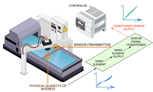
Fig 4. Signal conditioners applications
In which industry Signal Conditioning Circuitry is used?
Signal conditioning circuitry is used in a wide range of industries and sectors where accurate measurement, control, and communication of physical parameters are essential. Here are some of the industries where signal conditioning circuitry finds applications:
- Industrial Automation: Signal conditioning is widely used in manufacturing and process control systems to monitor and control variables like pressure, temperature, flow, and level. Industries include chemical processing, food and beverage, automotive manufacturing, and more.
- Instrumentation: Scientific instruments and laboratory equipment often rely on signal conditioning to enhance the accuracy and reliability of measurements. This includes oscilloscopes, spectrum analyzers, data loggers, and research equipment.
- Environmental Monitoring: Signal conditioning is used in environmental sensors and monitoring equipment for applications such as weather stations, air quality monitoring, water quality analysis, and soil condition assessment.
- Medical Devices: In the medical field, signal conditioning plays a critical role in devices like patient monitors, ECG machines, blood pressure monitors, and medical imaging equipment to ensure accurate measurement of physiological parameters.
- Aerospace and Aviation: Aerospace applications involve signal conditioning for monitoring parameters such as altitude, airspeed, engine performance, and navigation in aircraft and spacecraft.
- Automotive: Signal conditioning is employed in automotive electronics, including engine control units (ECUs), airbag systems, tire pressure monitoring systems (TPMS), and engine sensors.
- Telecommunications: Signal conditioning circuits are used in telecommunications equipment to improve signal quality and reliability, including applications in optical fiber communication, cellular networks, and satellite communication.
- Energy Management: In power systems and energy management, signal conditioning is utilized for monitoring voltage, current, power factor, and other electrical parameters in the electrical grid and renewable energy generation systems.
- Robotics: Robotics systems use signal conditioning for feedback control and sensors that provide information about joint positions, forces, and environmental conditions.
- HVAC and Building Automation: Heating, ventilation, and air conditioning (HVAC) systems, as well as building automation systems, use signal conditioning for temperature, humidity, and pressure sensors to maintain indoor comfort and energy efficiency.
- Test and Measurement: Signal conditioning is integral to test and measurement applications, including laboratory experiments and production line testing.
- Renewable Energy: Solar and wind power generation systems use signal conditioning to monitor and control variables such as solar irradiance, wind speed, and energy production.
- Oil and Gas Industry: Signal conditioning is applied in the oil and gas sector for measurements related to well drilling, reservoir monitoring, and pipeline control.
- Data Acquisition and Control Systems: Signal conditioning is fundamental in data acquisition systems used for research, monitoring, and control applications across various industries.
- Transportation: Various transportation systems, including trains, ships, and autonomous vehicles, utilize signal conditioning for sensor data processing and control.
These industries and sectors benefit from signal conditioning circuitry to ensure accurate, reliable, and meaningful data acquisition, control, and communication, ultimately contributing to improved efficiency, safety, and decision-making.
In which pressure device Signal Conditioning Circuitry is used?
Signal conditioning circuitry is commonly used in a variety of pressure measurement devices and sensors to enhance the accuracy, reliability, and compatibility of pressure signals. Here are some pressure devices and applications where signal conditioning circuitry is frequently employed:
- Pressure Transducers/Transmitters:
- Signal conditioning is integral to pressure transducers and transmitters used in various industries, such as industrial automation, automotive, and aerospace, to convert pressure into electrical signals. These devices often include amplification, offset adjustment, and temperature compensation.
- Barometric Pressure Sensors:
- Barometric pressure sensors, used in weather stations and environmental monitoring systems, may include signal conditioning to improve accuracy and provide stable readings under changing environmental conditions.
- Differential Pressure Sensors:
- Differential pressure sensors, commonly used in HVAC systems, filter monitoring, and flow measurement applications, utilize signal conditioning to process differential pressure readings accurately.
- Absolute Pressure Sensors:
- Absolute pressure sensors are employed in applications like altimeters, aviation, and meteorology. Signal conditioning helps in converting absolute pressure into electrical signals and provides compensation for temperature variations.
- Piezoresistive Pressure Sensors:
- Piezoresistive sensors, used in applications requiring high accuracy and sensitivity, often employ Wheatstone bridge configurations and signal conditioning to provide precise pressure measurements.
- Pressure Switches:
- Pressure switches with adjustable set points for applications like pressure control and safety monitoring may incorporate signal conditioning to ensure reliable switching.
- Hydraulic and Pneumatic Systems:
- In hydraulic and pneumatic systems, pressure sensors and transmitters equipped with signal conditioning are used for monitoring and controlling fluid pressure in industrial machinery.
- Tire Pressure Monitoring Systems (TPMS):
- TPMS sensors installed in vehicles include signal conditioning to convert tire pressure measurements into digital data for display on vehicle dashboards.
- Oil and Gas Industry:
- Pressure sensors and transmitters in the oil and gas sector use signal conditioning for applications such as wellhead monitoring, pipeline pressure control, and reservoir pressure measurement.
- Medical Devices:
- Signal conditioning is essential in medical pressure sensors used for blood pressure monitoring, respiratory therapy, and intracranial pressure measurement.
- Process Control:
- In industrial process control systems, signal conditioning is prevalent for pressure sensors used to regulate and monitor pressure levels in tanks, pipelines, and vessels.
- Environmental Monitoring:
- Pressure sensors in environmental monitoring systems, such as those used in groundwater monitoring and flood detection, may incorporate signal conditioning to ensure accurate pressure measurements.
- Aviation and Aerospace:
- Pressure sensors in aviation and aerospace applications, including aircraft altitude sensors and cabin pressure sensors, use signal conditioning to provide accurate altitude and pressure data.
Signal conditioning in pressure devices helps eliminate noise, compensate for temperature effects, and scale the signal to match the measurement range, ensuring reliable and precise pressure measurements across a wide range of applications and industries.
Installation and Maintenance
Does Signal Conditioning Circuitry need calibration?
Yes, signal conditioning circuitry, like many electronic components and systems, may require calibration to maintain accuracy and ensure reliable performance over time. Calibration is the process of comparing the actual output or response of a device or system to a reference standard or known values and making adjustments if discrepancies are detected. In the context of signal conditioning circuitry, calibration may be necessary for several reasons:
- Offset Correction: Signal conditioning circuits often include offset adjustments to ensure that the output is accurate when no input signal is present. Over time, components may drift or change, requiring periodic recalibration to maintain the correct zero-point reference.
- Gain Adjustment: Amplification circuits, which are common in signal conditioning, may require periodic calibration to ensure that the amplification factor (gain) remains accurate. This is crucial for maintaining the linearity of the output.
- Temperature Compensation: If the signal conditioning circuit includes temperature compensation components, they may need to be calibrated to ensure that they provide accurate compensation over a range of temperatures.
- Sensor Drift: Many signal conditioning circuits work in conjunction with sensors or transducers that can experience drift or changes in sensitivity over time. Calibration helps correct for these changes and maintains measurement accuracy.
- Nonlinearity Correction: In some applications, the sensors or transducers used may exhibit nonlinear behavior. Signal conditioning circuits can include linearization techniques that require calibration to maintain linearity in the output.
- Calibration Verification: Even if the signal conditioning circuitry itself is stable, it may be necessary to periodically verify its accuracy by comparing its output to a reference standard. This verification process can identify any long-term deviations from the expected performance.
- System Changes: Changes to the overall system, such as replacing components or sensors, can affect the calibration of the signal conditioning circuitry, necessitating recalibration.
The frequency of calibration depends on various factors, including the stability of the components, the criticality of accurate measurements, and the environmental conditions in which the circuitry operates. High-precision applications, such as medical devices, aerospace, and scientific instruments, often require more frequent calibration. Calibration procedures should be documented and performed by qualified personnel to ensure the continued accuracy and reliability of the signal conditioning circuitry and the associated measurement system.
How can measure the Signal Conditioning Circuitry accuracy?
Measuring the accuracy of signal conditioning circuitry involves comparing the circuit's output to a known reference value or standard to determine how closely it matches the expected or desired response. The accuracy measurement process can vary depending on the specific application and the parameters being measured. Here are steps you can follow to measure the accuracy of signal conditioning circuitry:
- Select a Reference Standard: Identify a reliable and accurate reference standard or measurement device that represents the physical parameter you are measuring (e.g., voltage, current, pressure, temperature).
- Establish Test Conditions:
-
Set up the signal conditioning circuitry and the reference standard in a controlled and stable environment. Ensure that the conditions, such as temperature and power supply voltage, are consistent throughout the measurement.
- Apply a Known Input: Provide a known input to the signal conditioning circuitry. This input should cover the range of measurements you intend to assess. For example, if measuring voltage, provide a known voltage signal.
- Record the Signal Conditioning Output: Measure and record the output signal from the signal conditioning circuitry under the test conditions. This is the response of the circuit to the known input.
- Compare to the Reference Standard: Compare the recorded output signal from the signal conditioning circuitry to the output of the reference standard. Calculate the difference between the two signals.
- Calculate Accuracy Metrics:
- Calculate accuracy metrics such as:
- Absolute Error: The magnitude of the difference between the measured output and the reference standard.
- Percentage Error: The absolute error expressed as a percentage of the reference value.
- Linearity Error: The deviation from a straight line when comparing the measured data points to the reference values across the measurement range.
- Repeat for Various Input Values:
- To assess the circuit's accuracy across its entire measurement range, repeat the process by applying different known input values and recording the corresponding output.
- Determine Accuracy Specifications:
- Compare the accuracy metrics obtained during testing to the circuit's specified accuracy in its datasheet or documentation. Determine if the circuit meets its accuracy specifications.
- Document Results:
- Document the results of the accuracy measurement, including the input values, measured output values, and calculated accuracy metrics. This documentation is essential for quality control and future reference.
- Perform Calibration (if necessary):
- If the accuracy falls outside acceptable limits, perform calibration adjustments as needed to bring the circuit's response within the specified accuracy range.
- Regular Maintenance and Reverification:
- Periodically reverify the accuracy of the signal conditioning circuitry, especially if it is used in critical applications. Regular maintenance and recalibration can help ensure consistent performance.
It's important to note that the accuracy of signal conditioning circuitry may depend on various factors, including the quality of components, environmental conditions, and the circuit's design. Therefore, accuracy measurements should be conducted under conditions representative of the actual operating environment to obtain meaningful results. Additionally, consult the circuit's documentation and specifications to understand its expected accuracy performance.
Important factors in choosing the right Signal Conditioning Circuitry for pressure transmitters?
Selecting the right signal conditioning circuitry for pressure transmitters is crucial to ensure accurate and reliable pressure measurements in a given application. Several important factors should be considered when making this choice:
- Pressure Range: Determine the range of pressures that the transmitter will be expected to measure. Ensure that the signal conditioning circuitry can accommodate this range and provide accurate measurements within it.
- Sensor Type: Different pressure sensors (e.g., piezoresistive, capacitive, piezoelectric) have different electrical characteristics. Ensure that the signal conditioning circuitry is compatible with the specific sensor type used in the pressure transmitter.
- Accuracy Requirements: Consider the required level of accuracy for your application. Some applications may demand high accuracy, while others can tolerate lower precision. Choose signal conditioning circuitry that meets or exceeds the required accuracy specifications.
- Environmental Conditions: Assess the environmental conditions in which the pressure transmitter will operate. Factors such as temperature, humidity, and exposure to chemicals or harsh environments can impact both the sensor and signal conditioning circuitry. Ensure that the selected components are suitable for these conditions.
- Output Signal Type: Determine the desired output signal type for the pressure transmitter. Common options include analog voltage, current (e.g., 4-20 mA), or digital outputs. The signal conditioning circuitry should match the desired output type and be compatible with the receiving equipment.
- Noise and Interference: Consider the presence of electromagnetic interference (EMI), radiofrequency interference (RFI), and other sources of noise in the environment. Choose signal conditioning circuitry with adequate noise filtering and shielding to ensure accurate measurements in noisy settings.
- Power Supply Requirements: Assess the available power supply voltage and current in your application. Ensure that the signal conditioning circuitry operates within the specified power supply range and voltage stability requirements.
- Response Time: Some applications require fast response times, while others can tolerate slower measurements. Select signal conditioning circuitry that provides the required response time for your application.
- Calibration and Maintenance: Consider the ease of calibration and maintenance. Some signal conditioning circuits may offer user-friendly calibration features, while others may require more complex procedures.
- Signal Isolation: If your application involves high-voltage or safety-critical environments, consider signal conditioning circuitry with isolation features to protect the equipment and personnel from electrical hazards.
- Compatibility with Control Systems: Ensure that the output signal of the signal conditioning circuitry is compatible with the control or data acquisition systems used in your application. Verify that communication protocols, voltage levels, and connectors align with your system requirements.
- Cost and Budget: Evaluate the cost of the signal conditioning circuitry and consider your budget constraints. Balance the cost with the required performance and features.
- Vendor Reputation and Support: Choose reputable vendors known for the quality and reliability of their signal conditioning products. Consider the availability of technical support and documentation.
- Scalability: If your application may expand or change in the future, consider whether the selected signal conditioning circuitry allows for scalability and adaptation to evolving needs.
- Regulatory Compliance: Ensure that the chosen signal conditioning circuitry complies with relevant industry standards and regulations, particularly if it's used in safety-critical or regulated applications.
By carefully evaluating these factors and conducting thorough research, you can make an informed decision when selecting signal conditioning circuitry for pressure transmitters, ensuring that it meets the specific requirements of your application.
Five Top Brands that produce Signal Conditioning Circuitry for Pressure Transiters
Several reputable brands produce signal conditioning circuitry for pressure transmitters and other industrial applications. Here are five top brands known for their quality signal conditioning products:
- Analog Devices, Inc. (ADI): Analog Devices is a well-respected manufacturer of analog and mixed-signal integrated circuits, including signal conditioning solutions for various sensors, including pressure transmitters.
- Texas Instruments (TI): Texas Instruments offers a wide range of signal conditioning and amplifier ICs suitable for pressure measurement applications. Their precision amplifiers and analog front-end products are commonly used in signal conditioning.
- Honeywell: Honeywell is a leading manufacturer of pressure sensors and transducers, and they often provide signal conditioning circuitry integrated into their pressure measurement solutions. Their signal conditioning products are designed for high accuracy and reliability.
- STMicroelectronics: STMicroelectronics manufactures a variety of semiconductor components, including signal conditioning ICs, amplifiers, and analog front-end devices that can be used in pressure transmitter applications.
- Microchip Technology: Microchip Technology produces analog and mixed-signal ICs, including signal conditioning components suitable for pressure sensors. Their product offerings include amplifiers, analog-to-digital converters (ADCs), and voltage references.
These brands are known for their commitment to quality, performance, and innovation in the field of signal conditioning, making them reliable choices for engineers and manufacturers seeking signal conditioning solutions for pressure transmitters and other sensor-based applications. When selecting a brand and specific product, it's important to consider your specific application requirements, including accuracy, environmental conditions, and compatibility with pressure sensors and control systems.
Conclusion
In conclusion, signal conditioning circuitry plays a critical role in a wide range of applications, including pressure measurement with transmitters. These circuits prepare, enhance, and optimize electrical signals from sensors to ensure accurate, reliable, and meaningful data acquisition, control, and communication within electronic systems. Key takeaways from our discussion include
- Purpose: The primary purpose of signal conditioning circuitry is to improve the quality of input signals, including amplifying weak signals, filtering out the noise, adjusting voltage or current levels, and compensating for temperature effects.
- Types: Signal conditioning circuitry comes in various types, including amplification, bridge circuitry, voltage scaling, current scaling (4-20 mA loop), offset adjustment, and temperature compensation, each serving specific functions in pressure measurement and other applications.
- Applications: Signal conditioning circuitry finds applications across industries such as industrial automation, aerospace, automotive, environmental monitoring, medical devices, telecommunications, and many others.
- Calibration: Signal conditioning circuitry may require periodic calibration to maintain accuracy and reliability, especially when used in precision applications. Calibration ensures that the circuitry's response matches expected values.
- Measurement of Accuracy: Accuracy measurement involves comparing the circuit's output to a known reference standard or value, considering factors such as offset correction, gain adjustment, and environmental conditions.
- Choosing the Right Circuitry: When selecting signal conditioning circuitry for pressure transmitters, consider factors like pressure range, sensor type, accuracy requirements, environmental conditions, output signal type, noise, and compatibility with control systems.
- Top Brands: Reputable brands that produce signal conditioning circuitry for pressure transmitters and other applications include Analog Devices (ADI), Texas Instruments (TI), Honeywell, STMicroelectronics, and Microchip Technology, known for their quality and reliability.
In summary, signal conditioning circuitry is an essential component in pressure measurement systems, ensuring that accurate and reliable pressure data is acquired and processed across a wide range of industries and applications. Careful consideration of the factors discussed is essential when choosing and maintaining signal conditioning circuitry to meet the specific needs of your application.
To recap
What is signal conditioning circuitry?
Signal conditioning circuitry is a set of electronic components and techniques used to prepare, enhance, and optimize electrical signals from sensors or transducers for accurate measurement, control, or communication.
Why is signal conditioning necessary?
Signal conditioning is necessary to improve signal quality, remove noise, compensate for sensor characteristics, and adapt signals to meet the requirements of downstream equipment.
What are the basic functions of signal conditioning?
Basic functions include amplification, filtering, scaling, linearization, offset adjustment, and temperature compensation.
In which industries is signal conditioning commonly used?
Signal conditioning is used in industries such as industrial automation, medical devices, aerospace, automotive, telecommunications, and environmental monitoring.
How does signal conditioning work?
It uses amplifiers, filters, and other components to modify input signals to meet specific requirements, such as noise reduction or voltage scaling.
What are some common types of signal conditioning circuitry?
Common types include amplification, bridge circuits, voltage scaling, current scaling (4-20 mA loop), offset adjustment, and temperature compensation.
Do signal conditioning circuits require calibration?
Yes, some signal conditioning circuits may require periodic calibration to maintain accuracy and reliability, especially in precision applications.
How is the accuracy of signal conditioning circuitry measured?
Accuracy is measured by comparing the circuit's output to a known reference standard or value and calculating metrics like absolute error and percentage error.
What factors should be considered when choosing signal conditioning circuitry for pressure transmitters?
Factors include pressure range, sensor type, accuracy requirements, environmental conditions, output signal type, noise, and compatibility with control systems.
What are some top brands that produce signal conditioning circuitry?
Reputable brands include Analog Devices (ADI), Texas Instruments (TI), Honeywell, STMicroelectronics, and Microchip Technology.
What is the purpose of temperature compensation in signal conditioning?
Temperature compensation corrects for variations in sensor performance due to temperature changes, ensuring accurate measurements over a wide temperature range.
What is the difference between signal amplification and voltage scaling?
Signal amplification increases the amplitude of a signal, while voltage scaling adjusts the signal's voltage levels without necessarily increasing its magnitude.
Is signal conditioning circuitry only used with analog sensors?
No, signal conditioning is used with both analog and digital sensors to optimize their output for processing and communication.
What role does signal conditioning play in data acquisition systems?
Signal conditioning prepares sensor signals for digitization, ensuring accurate and reliable data acquisition in systems like data loggers and measurement instruments.
Can signal conditioning circuitry be integrated into sensors or transmitters?
Yes, some sensors and transmitters have integrated signal conditioning circuitry to simplify system design and enhance accuracy.
References
https://www.designworldonline.com/signal-conditioner-basics/
Recent Posts
-

Booster Pump Troubleshooting and Maintenance: How to Fix and Prevent Common Issues
1. Introduction Imagine turning on your faucet only to be greeted with a weak trickle of water when …22nd Apr 2025 -

Energy-Efficient Booster Pumps: Selection and Tips for Maximizing Performance
1. Introduction Imagine never having to deal with fluctuating water pressure, noisy pumps, or skyroc …19th Apr 2025 -

Booster Pumps for Sustainable Water Systems: Irrigation and Rainwater Harvesting Solutions
1. Introduction Water scarcity is no longer a distant threat—it’s a reality affecting millions …16th Apr 2025