

Thermistor: Everything You Need to Know About These Tiny Temperature Sensors
History of Thermistor
Michael Faraday, an English scientist, first thought of the idea of a thermistor in 1833, when he was writing about how silver sulfide behaved as a semiconductor. During his research, he noticed that the resistance of silver sulfides decreased with increasing temperature. This discovery later led to the commercial production of thermistors in the 1930s, when Samuel Reuben invented the first commercial thermistor.
What is a Thermistor?
A thermistor, also called a thermal resistor, is a passive part whose resistance changes with the temperature in a system. Therefore, thermistors act as cheap, accurate, and dynamic tools for temperature measurement. The thermistor's resistance amount depends on the materials used to produce it. Usually, thermal resistors are made using ceramics or polymers.
Thermistors are used to monitor the temperature around a device and temperature changes in it. When a thermistor senses a temperature change, it affects the equipment. Thermistors are used to measure temperature and turn off equipment when it gets too hot. They can be found in many circuits, equipment, and other things. As we said, the thermistor is a type of resistance; it is also of the thermal resistance type.
Thermistor Symbol and Measurement Unit
Thermistors are ideal when accurate temperature readings are required. The circuit symbol of a thermistor is shown below:
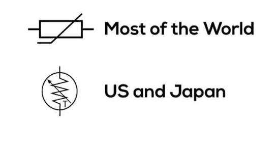
Fig 1. thermistor schematics
The unit of thermistor measurement is the same as the resistance in the ohm unit.
How Does a Thermistor Work?
A thermal resistor works because its resistance changes based on its temperature. We can measure the resistance of the thermistor using an ohmmeter. If we know the exact relationship between how temperature changes affect the thermistor resistance and its temperature, we can get its temperature by measuring the thermistor resistance. The amount of change in resistance depends on the type of material used in thermal resistance. The relationship between temperature and thermistor resistance is non-linear. A typical thermal resistance diagram is shown below (Figure 2).
If we have a thermistor with a high-temperature graph, we can adjust the resistance measured by the ohmmeter to the temperature shown on the diagram. We can find the temperature of the thermal resistance by drawing a horizontal line against the resistance on the y-axis and a vertical line down from where this horizontal line crosses the graph.
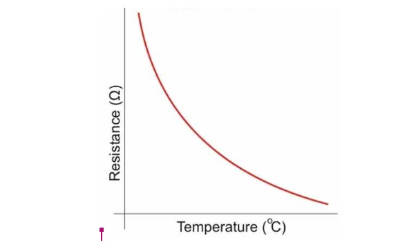
Fig 2. non-linear relationship between temperature and thermistor resistance
Thermal Resistance Structure
To make a thermal resistor, two or more semiconductor powders made of metal oxides are mixed with an adhesive to create a thin material. Little drops of this diluted substance form on the lead wires.
To dry, we have to put it in a baking oven. During this process, a thin material is deposited on the lead wires to form an electrical connection. This processed metal oxide is sealed by placing a glass cover over it. This glass coating gives the thermistors waterproof properties and helps to improve their stability.
Various shapes and sizes of thermal resistances are available in the market; Smaller thermal resistors are in the form of beads with a diameter of 0.15 mm to 1.5 mm. Thermistor resistors may also be in the form of discs and washers, which are made by pressing the thermistor material under high pressure into flat cylindrical shapes with a diameter of 3 mm to 25 mm.

Fig 3. Different shapes and sizes of thermal resistances
The typical size of a thermistor is 0.125 to 1.5 mm. The thermal resistors available in the market have nominal values of 1K, 2K, 10K, 20K, 100K, etc. This value represents the resistance value at 25 °C. Thermistors are available in different models: bead type, rod type, disk type, etc. One of the best things about thermal resistances is that they are small and not too expensive.

Fig 4. Various models of thermistors
Types of Thermistor
Thermistors are generally divided into two categories:
- NTC-type thermistors
- PTC-type thermistor
NTC-Type Thermistors
An NTC-type thermistor (negative temperature coefficient thermistor) is also called a negative thermal coefficient thermistor, or NTC temperature sensor. In this type of thermistor, as the temperature increases, the resistance decreases. Therefore, in an NTC thermistor, temperature and resistance are inversely proportional. This type of resistance is the most common type of thermal resistance. NTC thermistors are reliable and stable, and they are better equipped than other temperature sensors to deal with environmental conditions and noise immunity.
The following equation shows how the resistance of an NTC thermistor changes with the temperature:

Fig 5. This graph depicts how the the resistance of NTC changes with temperature.

- RT is The resistance measured at T (K).
- R0 is The resistance in temperature (K).
- T0 is the reference temperature (usually 25°C)
- β is a constant, the value of which depends on the properties of the material. Usually, the nominal value is 4000.
If the beta is large, the relationship between resistance and temperature will be excellent. With a higher beta value, the resistance changes more when the temperature goes up by the same amount. It means that the thermal resistance is more sensitive and accurate.
PTC-Type Thermistor
A PTC type thermistor is also called a positive temperature coefficient, the positive thermal coefficient thermistor or PTC sensor. In this type of thermistor, as the temperature increases, the resistance also increases. Therefore, in a PTC thermistor, temperature and resistance are directly proportional.
Although not as common as NTC thermistors, PTC thermistors are often used as a type of circuit protector. Similar to the function of fuses, PTC thermistors can act as current-limiting devices. As the current passes through the device creates a small amount of resistive heating. If the current is high enough to generate more heat than the device can lose to its surroundings, the device will overheat. This heating increases the resistance of the PTC thermistor.
Thermistors are available on the market in both surface and pedestal mounting types. SMD thermal resistance is the more common type that is used by electronic engineers because SMD installation provides much better temperature stability for circuits.

Fig 6. This graph depicts how the the resistance of NTC changes with temperature.
Applications of Thermistors
Thermistors are used in the following ways:
- As mentioned before, thermistors are compact; Therefore, they can be used as a temperature sensor in digital thermometers or thermostats.
- In the automotive industry, they can be used to measure coolant and oil temperatures in trucks and cars.
- Thermal resistance is used to change the amount of heat that home appliances need.
- A thermistor is used to protect circuits from the effect of an overload, which is the result of an increase in resistance. Hence, thermistors also act as circuit protectors.
- Thermal resistance is used in rechargeable batteries, and circuits of electronic devices.
- Generation of analog output voltage in response to ambient temperature changes
- Temperature monitoring in weather systems, laundry, dishwasher, 3D printer, etc.
Application of NTC and PTC Thermistors
Some applications of NTC and PTC thermistors are:
- temperature compensation
- Temperature measurement
- Temperature control
- Inrush current limitation
What Causes Thermal Resistance to Fail?
If the lead and resistor get physically separated and cause an open circuit, the thermistor will break. This could happen if the lead and resistor are handled incorrectly or if the heat damage is not fixed. This is one of the reasons for the failure of the thermal resistance. Another reason could be the aging of the thermistor. Because of these things, the temperature values change, and a set of wrong temperature values is shown. This problem can be solved by replacing the thermistor.
How to Test the Thermistor Sensor
We can use an analog multimeter to test the thermistor sensor. The steps that are performed to test thermal resistances are:
- Connect the analog multimeter to the thermal resistance wires; Polarity does not matter.
- We can heat the thermistor by using an iron soldering.
- When the heat tends to change in the thermistor, the readings on the multimeter will increase or decrease approximately.
- The graphical analysis is based on the selected PTC or NTC thermistor type.
- For healthy thermal resistors, the change in writing is smooth and without problems.
Advantages and Disadvantages of a Thermistor
Some of the Advantages of Thermistors are:
- Compact size
The existence of various packages allows thermal resistance to work in small or tight spaces. As a result, they occupy less space on printed circuit boards.
- Fast response time
Their small size lets them respond quickly to changes in temperature, especially when feedback is needed right away.
- Cost-Effective
If the thermistor you buy has the right RT curve, not only are they cheaper than other temperature sensors, but they also don't need to be calibrated again during installation or the rest of their lives.
- Adaptability
The ability to obtain a specific resistance at a specific temperature
- Curve matching
interchangeable thermal resistances with an accuracy of +0.1 to +2 °C.
- High sensitivity and accuracy compared to other sensors
- Comfortable and easy to use
The Following are Some of the Disadvantages of Thermistors:
- They are non-linear; Especially at high temperatures
- It is fragile.
- It has a limited working temperature range.
- They need protection on the power lines.
- The resistance value of a thermistor changes as the temperature changes. Because they are sensitive to small temperature changes, they are good for situations where a certain temperature must be maintained. Depending on the type of thermistor, it can measure liquid, gas, or solid temperatures.
Conclusion
Thermal resistors are the best way to measure and control the temperature of a thermoelectric cooler as part of a temperature control system because of their ability to adjust in several stages. The closer the thermal resistance is to the device to be monitored, the better the result will be.
Recent Posts
-

Booster Pump Troubleshooting and Maintenance: How to Fix and Prevent Common Issues
1. Introduction Imagine turning on your faucet only to be greeted with a weak trickle of water when …22nd Apr 2025 -

Energy-Efficient Booster Pumps: Selection and Tips for Maximizing Performance
1. Introduction Imagine never having to deal with fluctuating water pressure, noisy pumps, or skyroc …19th Apr 2025 -

Booster Pumps for Sustainable Water Systems: Irrigation and Rainwater Harvesting Solutions
1. Introduction Water scarcity is no longer a distant threat—it’s a reality affecting millions …16th Apr 2025