

Load Cell Troubleshooting
Precision in Motion: Unlocking the Potential of Load Cells through Comprehensive Troubleshooting and Optimization
Load cells are designed to detect force or weight under unfavorable situations; they are not only an essential component of an electronic weighing system but also the most susceptible.
Ingress of chemicals or moisture, improper handling, vibration, internal component failure, overloading (shock), lightning strikes, or heavy electrical surges generally can all cause damage to load cells.
Load cell troubleshooting involves identifying and resolving common issues such as overloading, non-linearity, temperature effects, creep, hysteresis, electrical noise, compatibility issues, and wiring problems. By understanding these challenges and implementing effective troubleshooting techniques, operators can maintain the optimal functionality of load cells and obtain accurate measurements.
This research aims to provide a comprehensive guide to load cell troubleshooting, offering insights and practical solutions for each specific issue. Whether you are an engineer, technician, or user working with load cells, this research will equip you with the knowledge and techniques needed to diagnose and resolve problems, enhancing the reliability and performance of load cell systems.
Load cell fundamental parts and installation
The scale or system may drift, produce unstable or incorrect readings, or fail to record.
The performance of a load cell force (or weight) measuring system is based on the physical installation's integrity, accurate connectivity of the components, the proper performance of the main components that comprise the system, and system calibration.
If the installation was initially operational and properly calibrated, troubleshooting could start by checking each part separately to see if it has been damaged or has malfunctioned.
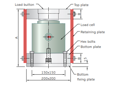
Fig 1. Load cell construction
The fundamental parts are:
- Load cells
- Mechanical supports and load connections
- Interconnecting cables
- Junction boxes
- Signal conditioning electronics
Mechanical Installation
Load Cells not installed according to the manufacturer's guidelines may not perform as expected. It is always beneficial to check:
- Installing surfaces for cleanliness, flatness, and alignment
- All mounting hardware torque
- Load cell orientation: Live end attached to the load to be measured, dead-end connected to mechanical reference or load forcing source. (A dead end is an end that is mechanically closest to a connector or cable exit.)
- Connecting the load to the load cell requires Interface-recommended hardware (thread diameters, jam nuts, swivels, etc.).
- One of the most important rules is that there can only be one load path. This load path must pass via the load cell's load axis. Although it may seem simple, this issue is frequently disregarded.
Electrical Installation
The proper load cell operation is also affected by the electrical system. The following are examples of common problem areas:
- Loose or soiled electrical connections or faulty color-coded wire connections.
- Failure to employ remote excitation voltage sensing over long connections.
- Incorrect excitation voltage setting. (The optimal setting is 10 VDC, as this is the voltage used to calibrate the load cell at the factory. The maximum permissible voltage is 15 or 20 volts depending on the model. Some battery-powered signal conditioners use as low as 1.25 volts to preserve energy.)
- Bridge circuit Loading. (Extremely accurate load cell systems necessitate highly accurate read-out instruments. These types of devices often have very high input impedances to prevent circuit loading errors.).
- Input and output resistances. If these are more significant than 3k, the load cell is often faulty due to electrical surges or lightning.
- Separate resistance of strain gauges.
- Make sure the input and output resistance are within the product's permitted tolerance by measuring them with a multimeter (resistance accuracy of 0.025 or better).
- Check the certificate of calibration. A difference of more than 0.1 indicates a faulty load cell.
- Check the insulation of the wire leads connecting to the load cell's metal body using a multimeter. The insulation is poor if the resistance is less than 2 Giga. The ideal insulating resistance is better than 5 Giga.
- Connect the load cell to a steady power source and measure the mV/V output as in the previous step to check for zero return. Ensure that it is within the acceptable tolerance. Load the load cell for 5 seconds at 50% to 100% capacity. Check if the mV/V output returns to the acceptable tolerance after removing the load.
- Place the load cell without a load applied to check for zero balance. Connect the input to a low-noise, steady power source. Measure the output voltage in mV using a multimeter, then divide it by the input voltage in V to obtain mV/V. Refer to the load cell's calibration certificate to determine if this mV/V value falls within the load cell's tolerance range.
Load Cell Troubleshooting
If you're experiencing issues with a load cell, there are several troubleshooting steps you can take to identify and potentially resolve the problem. Here are some common troubleshooting tips:
- Check the connections: Ensure that all the electrical connections between the load cell and the associated equipment are secure. Verify that the wiring is correctly connected according to the load cell's specifications.
- Power supply: Confirm that the load cell is receiving the proper power supply voltage. Check if the power source is functioning correctly and supplying the required voltage.
- Load cell wiring: Examine the load cell's wiring for any signs of damage, such as frayed or broken wires. If you find any issues, repair or replace the wiring as necessary.
- Grounding: Verify that the load cell is properly grounded. Grounding helps eliminate electrical noise and interference. Ensure that the ground connections are secure and clean.
- Environmental factors: Evaluate the operating environment for any factors that may be affecting the load cell's performance. Check for excessive vibration, temperature fluctuations, or moisture, as these can impact the load cell's accuracy and reliability.
- Calibration: If the load cell is not providing accurate readings, it might require calibration. Consult the load cell's documentation or the manufacturer's guidelines for instructions on how to calibrate it properly.
- Interference: Assess if there are any potential sources of electromagnetic interference (EMI) nearby. EMI can disrupt the load cell's signal. Remove or shield any EMI sources, such as power cables or electrical equipment, from the vicinity of the load cell.
- Equipment compatibility: Ensure that the load cell is compatible with the associated equipment, such as data acquisition systems or indicators. Check that the load cell's specifications match the requirements of the equipment it is connected to.
- Consult the manufacturer: If you have followed the troubleshooting steps and the issue persists, it is recommended to reach out to the load cell manufacturer or their technical support for further assistance. They can provide specific guidance tailored to your load cell model.
Remember to always follow safety protocols and guidelines while troubleshooting any electrical or mechanical equipment.
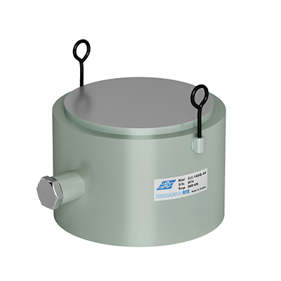
Fig 2. Resistive Strain Gauge
What problems do we face while using the load cell?
While using load cells, several problems can arise that may affect their performance and accuracy. Here are some common issues faced when working with load cells:
- Overload or Overcapacity: Applying a load that exceeds the load cell's rated capacity can cause damage or affect its accuracy. It's crucial to ensure that the load applied to the load cell remains within its specified range.
- Non-Linearity: Load cells may exhibit non-linear behavior, meaning that the output signal may not increase or decrease linearly with the applied load. This can lead to inaccuracies in measurement and may require compensation or calibration.
- Temperature Effects: Temperature changes can affect the load cell's performance, leading to variations in readings. Temperature compensation techniques or using temperature-compensated load cells can help mitigate this issue.
- Creep: Creep refers to the gradual deformation of the load cell under a sustained load over time. It can result in inaccurate readings if not accounted for or if the load cell is not designed to handle such conditions.
- Hysteresis: Hysteresis is the difference in load cell output for the same applied load, depending on whether the load is increasing or decreasing. This behavior can introduce errors in measurements, particularly when there are rapid load changes.
- Electrical Noise: Electrical noise, such as electromagnetic interference (EMI), can interfere with the load cell's signal, leading to erroneous readings. Proper grounding and shielding techniques can help reduce the impact of electrical noise.
- Environmental Factors: Environmental conditions like humidity, moisture, dust, and vibration can affect the load cell's performance. Load cells designed for specific environmental conditions may be required in such situations.
- Mounting and Installation: Improper mounting or installation of load cells can lead to mechanical stresses, misalignment, or strain on the load cell, resulting in inaccurate measurements.
- Compatibility Issues: Using load cells with incompatible equipment or not following the recommended wiring and connections can cause measurement problems. It's essential to ensure that the load cell is compatible with the associated equipment and properly integrated.
- Wiring and Connection Problems: Faulty wiring, loose connections, or damaged cables can disrupt the signal transmission and lead to measurement errors. Regular inspection of the load cell's wiring is important to identify and address any issues.
To troubleshoot these problems, refer to the load cell's documentation, consult the manufacturer's guidelines, and follow best practices for installation, calibration, and maintenance. If issues persist, contacting the load cell manufacturer or their technical support can provide further assistance.
Fig 3. Vibrating Wire Hydraulic Center Hole-Anchor Bolt Load Cell
How can troubleshoot when overload happened?
When an overload occurs with a load cell, it is essential to take appropriate steps to assess the situation and minimize any potential damage. Here's how you can troubleshoot when an overload happens with a load cell:
- Immediately remove the overload: Once you realize that an overload has occurred, remove the excessive load from the load cell as quickly as possible. This will help prevent further damage to the load cell.
- Inspect the load cell visually: Perform a visual inspection of the load cell for any visible signs of damage or deformation. Look for bent or distorted components, fractures, or any other noticeable issues. If you observe severe physical damage, it may indicate that the load cell needs to be replaced.
- Check the load cell specifications: Refer to the load cell's specifications and documentation to understand its rated capacity and overload limits. Compare the applied load with the load cell's capacity to determine the extent of the overload. If the overload exceeds the load cell's rated capacity, the load cell may have suffered permanent damage.
- Calibrate or re-zero the load cell: After removing the overload, it's recommended to recalibrate or re-zero the load cell. This will help restore the load cell's accuracy if any drift or deviation occurred during the overload. Follow the load cell manufacturer's instructions or calibration procedures for the specific model you are using.
- Perform functional tests: Once the load cell has been recalibrated or re-zeroed, perform functional tests to check its performance. Apply a known load within the load cell's rated capacity and observe if the readings are consistent and accurate. Monitor the load cell for any signs of instability, drift, or abnormal behavior.
- Monitor for long-term effects: Even if the load cell appears to be functioning correctly after an overload, it's important to monitor its performance over time. Keep an eye out for any unexpected changes, such as increased drift, reduced accuracy, or other abnormalities. Continued monitoring can help identify any latent damage that may have occurred during the overload.
- Consult the manufacturer or a professional: If you have concerns about the load cell's performance or suspect significant damage, it is advisable to contact the load cell manufacturer or consult with a professional technician. They can provide further guidance and assistance based on the specific circumstances.
Remember, overloading a load cell can potentially cause irreversible damage. It is crucial to follow the load cell's specifications, ensure proper usage, and avoid exceeding its rated capacity to maintain its accuracy and reliability.
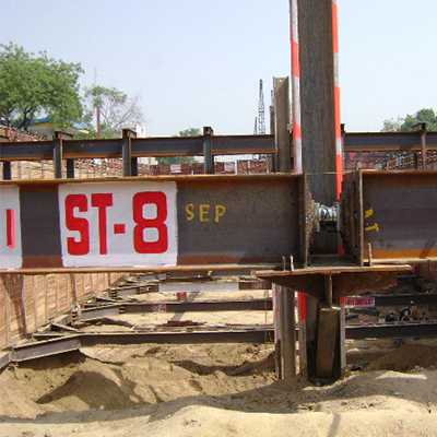
Fig 4. The compression load cell in between the strut at an under-construction metro station
How can troubleshoot when Non-Linearity happened?
When non-linearity occurs in a load cell, where the output signal does not increase or decrease linearly with the applied load, you can take the following steps to troubleshoot the issue:
- Confirm the load cell's specifications: Review the load cell's specifications and documentation to understand its expected linearity performance. Check the manufacturer's specified linearity error or linearity deviation. Ensure that the load cell is within its specified operating range.
- Check the load cell's calibration: Verify if the load cell has been properly calibrated. Improper calibration can introduce non-linearity. Refer to the load cell's calibration procedure and ensure that it has been carried out correctly.
- Examine the applied load conditions: Analyze the load conditions under which non-linearity is observed. Determine if there are any specific factors or variations in the applied load that could be causing the non-linear behavior. Consider factors such as load distribution, load application speed, and load stability.
- Perform multiple load tests: Conduct several load tests at different load points within the load cell's operating range. Record the load cell's output readings at each load point. Plot a calibration curve or graph using the obtained data points. Compare the curve with the expected linear response. This will help identify any deviations or non-linear patterns.
- Apply load reversal: If the load cell exhibits non-linearity during load reversal (increasing and decreasing load cycles), perform load reversal tests. Apply loads in both directions (increasing and decreasing) and observe if the load cell's output exhibits consistent behavior. Non-linearity during load reversal may indicate issues related to hysteresis.
- Consider environmental factors: Environmental conditions, such as temperature fluctuations or vibration, can affect a load cell's linearity. Evaluate if any environmental factors may be contributing to the non-linear behavior. Use temperature-compensated load cells or take steps to minimize environmental influences if necessary.
- Verify wiring and connections: Check the load cell's wiring and connections to ensure they are secure and properly connected. Faulty or loose connections can introduce signal disturbances that may lead to non-linear behavior. Ensure that the wiring is correct and that there are no damaged or frayed wires.
- Consult the manufacturer or a professional: If you have followed the troubleshooting steps and are unable to resolve the non-linearity issue, it is advisable to contact the load cell manufacturer or consult with a professional technician. They can provide further guidance, perform advanced tests if required, or recommend potential solutions.
Note that some level of non-linearity is expected in load cells, but it should be within the manufacturer's specified limits. If the non-linearity exceeds the acceptable range, it may affect the load cell's accuracy and may require additional calibration or adjustment.
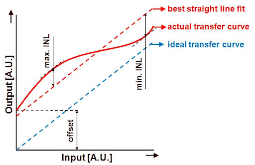
Fig 5. Non-linearity
How can troubleshoot when Temperature Affects the result?
When temperature effects impact the results of a load cell, causing variations in readings, you can take the following steps to troubleshoot the issue:
- Understand temperature specifications: Review the load cell's documentation and specifications to understand its temperature range and any temperature-related performance specifications provided by the manufacturer. Ensure that the load cell is being used within its specified temperature range.
- Measure ambient temperature: Check the ambient temperature in the area where the load cell is being used. Variations in ambient temperature can affect the load cell's performance. Ensure that the temperature remains within the load cell's specified range.
- Monitor temperature changes: Observe if there are significant temperature fluctuations during the load cell's operation. Rapid temperature changes can impact the load cell's readings. Identify any patterns or correlations between temperature changes and variations in the load cell's output.
- Apply temperature compensation techniques: Implement temperature compensation techniques to minimize the impact of temperature changes on the load cell's readings. Temperature compensation can involve using temperature sensors, employing compensation algorithms, or utilizing temperature-compensated load cells. Consult the load cell's documentation or manufacturer's guidelines for specific temperature compensation methods.
- Calibrate the load cell: Perform regular calibration of the load cell to account for temperature effects. Calibration adjusts the load cell's output based on the current temperature conditions. Follow the load cell's calibration procedure, which may include applying known loads at specific temperatures and adjusting the readings accordingly.
- Evaluate thermal isolation: Assess if the load cell is adequately isolated from external temperature sources. Ensure that there are no nearby heat-emitting devices, direct exposure to sunlight, or drafts that could influence the load cell's temperature. Consider using thermal barriers or insulation to minimize temperature effects.
- Install temperature control mechanisms: If temperature variations are excessive and affect the load cell's performance, consider implementing temperature control mechanisms in the operating environment. This can involve maintaining stable ambient temperature through air conditioning, insulation, or temperature-regulated enclosures.
- Consult the manufacturer or a professional: If the temperature effects persist and troubleshooting steps do not yield satisfactory results, it is recommended to contact the load cell manufacturer or consult with a professional technician. They can provide specific guidance and assistance tailored to your load cell model and the specific temperature-related issues you are experiencing.
By implementing temperature compensation techniques, regular calibration, and maintaining stable environmental conditions, you can minimize the impact of temperature on load cell readings and improve the accuracy and reliability of measurements.
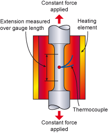
Fig 6. Creep failure affected by temperature
How can troubleshoot when Creep happened?
When creep occurs in a load cell, which refers to the gradual deformation of the load cell under a sustained load over time, you can take the following steps to troubleshoot the issue:
- Remove the load: If you notice creep in the load cell, remove the load from the load cell as soon as possible. This will help prevent further deformation and potential damage.
- Verify load and time conditions: Review the load and time conditions under which creep is observed. Note the magnitude of the load applied and the duration for which it was sustained. This information will help in assessing the extent of the creep and its potential causes.
- Check load cell specifications: Refer to the load cell's specifications and documentation to understand its creep specifications. Load cells usually have a specified creep rate or creep limit. Compare the observed creep with the manufacturer's specifications to determine if it falls within the acceptable range.
- Evaluate load distribution and mounting: Assess the load distribution and how the load is applied to the load cell. Improper load distribution or uneven mounting can contribute to increased stress on specific areas of the load cell, leading to creep. Ensure that the load is distributed evenly and that the load cell is securely and properly mounted.
- Inspect for physical damage: Perform a visual inspection of the load cell for any visible signs of damage or deformation. Look for bent or distorted components, fractures, or any other noticeable issues. Physical damage can contribute to creep and may require the replacement of the load cell.
- Consider load cell material: Different load cell materials have varying resistance to creep. If the creep is excessive or persistent, consider using load cells made of materials specifically designed to minimize creeps, such as alloy steel or stainless steel.
- Apply periodic load cycling: Implement periodic load cycling to help reduce or alleviate creep in the load cell. This involves applying load and then unloading the load cell at regular intervals. Load cycling can help redistribute stresses and prevent creep from accumulating over time.
- Monitor and document creep behavior: Continuously monitor the load cell's behavior over time to assess the rate of creep and any changes. Document the load and time conditions, as well as the observed creep, to establish a pattern or identify potential triggers.
- Consult the manufacturer or a professional: If the creep issue persists or worsens, it is advisable to contact the load cell manufacturer or consult with a professional technician. They can provide further guidance, perform advanced tests if necessary, or recommend potential solutions.
Remember, excessive creep can lead to significant inaccuracies in load measurements and may indicate a compromised load cell. Regular maintenance, proper load distribution, and adherence to load cell specifications can help minimize and manage creep.
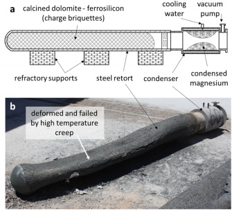
Fig 7. Creep failure
How can troubleshoot when Hysteresis happened?
When hysteresis occurs in a load cell, which refers to the difference in output readings for the same load applied in the increasing and decreasing directions, you can take the following steps to troubleshoot the issue:
- Verify load cell specifications: Review the load cell's specifications and documentation to understand its hysteresis specifications. Load cells typically have a specified hysteresis limit or hysteresis error. Compare the observed hysteresis with the manufacturer's specifications to determine if it falls within the acceptable range.
- Perform load reversal tests: Conduct load reversal tests by applying loads in both the increasing and decreasing directions. Monitor and record the load cell's output readings for each load reversal cycle. Compare the readings to check if there is a noticeable difference between the increasing and decreasing load directions.
- Evaluate load application speed: Vary the speed at which the load is applied to the load cell during load reversal tests. Hysteresis can be influenced by the rate at which the load is applied. Slowly increasing or decreasing the load speed can help identify if the hysteresis behavior changes.
- Check load cell mounting and alignment: Ensure that the load cell is properly mounted and aligned. Misalignment or uneven loading can contribute to hysteresis. Verify that the load is applied uniformly and centered on the load cell to minimize any potential sources of error.
- Inspect for physical damage: Perform a visual inspection of the load cell for any visible signs of damage or deformation. Look for bent or distorted components, fractures, or any other noticeable issues. Physical damage can contribute to hysteresis and may require the replacement of the load cell.
- Calibrate the load cell: Calibration can help compensate for hysteresis effects by adjusting the load cell's output readings. Follow the load cell's calibration procedure, which may involve applying loads in specific directions and adjusting the readings accordingly. Regular calibration can minimize the impact of hysteresis.
- Consider load cell material and design: Different load cell materials and designs have varying degrees of hysteresis. If hysteresis is a persistent issue, consider using load cells with improved hysteresis performance, such as those made of high-quality materials or utilizing advanced design features.
- Consult the manufacturer or a professional: If hysteresis persists or worsens, it is advisable to contact the load cell manufacturer or consult with a professional technician. They can provide further guidance, perform advanced tests if necessary, or recommend potential solutions tailored to your load cell model.
By following these troubleshooting steps, you can identify potential causes of hysteresis and work towards minimizing its impact on load cell readings. Regular calibration, proper load application, and adherence to load cell specifications are essential for accurate and reliable measurements.
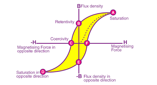
Fig 8. Hysteresis loop
How can troubleshoot when electrical noise happened?
When electrical noise occurs in a load cell, causing interference and inaccurate readings, you can take the following steps to troubleshoot the issue:
- Check the power supply: Ensure that the load cell is receiving a stable and clean power supply. Verify that the voltage levels are within the load cell's specified range. If possible, use a dedicated power source for the load cell to minimize potential interference from other devices.
- Inspect the wiring and connections: Examine the load cell's wiring and connections for any loose, damaged, or improperly shielded wires. Poorly connected or exposed wires can pick up electrical noise from the surrounding environment. Secure and properly shield the wires to reduce interference.
- Use shielded cables: Employ shielded cables for connecting the load cell to the measuring instrument or data acquisition system. Shielded cables help reduce the impact of external electromagnetic interference on the load cell's signal. Ensure that the shields are properly grounded at both ends.
- Eliminate nearby sources of interference: Identify and eliminate or relocate any nearby sources of electrical interference. This includes power cables, motors, transformers, or other devices that generate electromagnetic fields. Keep the load cell away from such sources to minimize interference.
- Apply filtering techniques: Install appropriate filters to reduce electrical noise. This can include adding low-pass filters or noise filters to the load cell's signal conditioning circuitry. Filters can help attenuate high-frequency noise that may be affecting the load cell's readings.
- Grounding and shielding: Ensure proper grounding of the load cell and associated equipment. Establish a solid ground connection by connecting the load cell's grounding terminal to a reliable and dedicated ground point. Additionally, consider using electromagnetic shielding around the load cell and signal cables to minimize interference.
- Use differential measurement: If possible, employ a differential measurement configuration. This involves using two identical load cells in an opposite configuration, with one in tension and the other in compression. By taking the difference between their output signals, common-mode electrical noise can be effectively canceled out.
- Test in different environments: If electrical noise persists, test the load cell in different environments or locations to determine if the noise is specific to a particular area. This can help identify external factors contributing to the interference.
- Consult the manufacturer or a professional: If troubleshooting steps do not resolve the electrical noise issue, it is recommended to contact the load cell manufacturer or consult with a professional technician. They can provide specific guidance, recommend advanced noise reduction techniques, or suggest alternative solutions.
Minimizing electrical noise is crucial for accurate load cell measurements. By addressing power supply issues, ensuring proper grounding and shielding, and implementing filtering techniques, you can significantly reduce the impact of electrical noise on load cell readings.

Fig 9. Electrical noise on load cell output signal
How can troubleshoot when environmental factors affect the load cell?
When environmental factors affect a load cell, causing variations in readings, you can take the following steps to troubleshoot the issue:
- Review load cell specifications: Consult the load cell's specifications and documentation to understand its recommended operating conditions and environmental limitations. Ensure that you are using the load cell within its specified temperature, humidity, and other environmental ranges.
- Assess temperature variations: Monitor the temperature in the environment where the load cell is located. Extreme temperature fluctuations can impact the load cell's performance. Ensure that the temperature remains within the load cell's specified range. Consider using temperature-compensated load cells if temperature variations are significant.
- Evaluate humidity levels: Excessive humidity can affect the load cell's accuracy and performance. Monitor and control humidity levels in the operating environment, especially if the load cell is not specifically designed to handle high humidity conditions. Consider using load cells with appropriate sealing or protective measures for humid environments.
- Minimize vibration and shock: Excessive vibration or shock can introduce errors in load cell readings. Identify and reduce any sources of vibration or shock near the load cell. Secure the load cell and its mounting to minimize the effects of external disturbances.
- Check for electromagnetic interference (EMI): EMI from nearby electronic equipment, power lines, or other sources can cause interference and affect the load cell's performance. Identify potential sources of EMI and relocate the load cell or the interfering devices to minimize the impact. Use shielded cables and grounding techniques to reduce EMI effects.
- Inspect for contamination: Environmental contaminants, such as dust, dirt, moisture, or chemicals, can affect the load cell's operation. Regularly inspect the load cell for any signs of contamination and clean it following the manufacturer's guidelines. Consider using load cells with appropriate protection, such as IP-rated enclosures, for harsh or contaminated environments.
- Perform calibration and verification: Regular calibration is essential to account for environmental effects on the load cell. Follow the load cell's calibration procedure, adjusting the readings based on the current environmental conditions. Periodically verify the load cell's performance to ensure it meets the required accuracy.
- Consult the manufacturer or a professional: If environmental factors continue to impact the load cell despite troubleshooting steps, it is advisable to contact the load cell manufacturer or consult with a professional technician. They can provide specific guidance, recommend suitable environmental protection measures, or suggest alternative load cell options.
Addressing environmental factors that affect the load cell requires careful consideration of temperature, humidity, vibration, EMI, and contamination. By monitoring the environment, minimizing disturbances, and implementing appropriate protection measures, you can optimize the load cell's performance and maintain accurate readings.
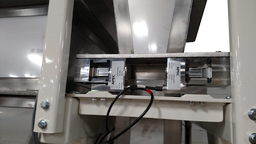
Fig 10. The load cell in the industry
How can troubleshoot the mounting and installation problems?
When encountering issues related to mounting and installation of a load cell, you can take the following steps to troubleshoot the problem:
- Inspect the mounting hardware: Check the load cell's mounting hardware, including bolts, screws, brackets, and mounting plates. Ensure that all components are securely tightened and properly aligned. Loose or misaligned mounting hardware can cause measurement errors and affect the load cell's performance.
- Verify load cell alignment: Ensure that the load cell is aligned correctly and in the intended orientation. Improper alignment can lead to uneven loading, increased stress concentrations, or incorrect load distribution, resulting in inaccurate readings. Refer to the load cell's documentation for specific alignment guidelines.
- Evaluate the mounting surface: Check the mounting surface for flatness and evenness. Ensure that it provides adequate support and stability for the load cell. A non-flat or uneven mounting surface can introduce stress concentrations and affect the load cell's accuracy. Consider using shims or leveling devices to achieve a level and stable mounting surface.
- Consider mounting accessories: Evaluate if any mounting accessories or adapters are required for the load cell installation. Some load cells may need additional components to ensure proper alignment, load distribution, or protection against external forces. Follow the load cell manufacturer's recommendations regarding mounting accessories, if applicable.
- Minimize external forces: Identify and minimize external forces acting on the load cell during installation. Avoid any excessive bending, twisting, or lateral forces that could strain the load cell or compromise its integrity. Ensure that the load cell is not subjected to vibrations, shocks, or impacts during installation or operation.
- Check cable routing: Verify the routing of the load cell's cables. Ensure that they are not excessively stretched, bent, or pinched. Improper cable routing can cause strain on the connections and lead to signal interference or connection issues. Maintain adequate cable slack and use cable clamps or conduits to secure and protect the cables.
- Perform a zero-load calibration: Conduct a zero-load calibration after mounting the load cell to establish a reference point. This calibration helps account for any inherent errors introduced during the installation process. Follow the load cell's calibration procedure and adjust the readings accordingly.
- Consult the load cell manufacturer or a professional: If the mounting and installation issues persist or if you are uncertain about the correct installation procedure, it is recommended to contact the load cell manufacturer or consult with a professional technician. They can provide specific guidance, offer recommendations, or assist in resolving any mounting-related problems.
By ensuring proper mounting, alignment, and installation of the load cell, you can minimize errors and improve the accuracy and reliability of the load measurements. Following manufacturer guidelines and seeking expert assistance when needed will help you troubleshoot mounting and installation issues effectively.
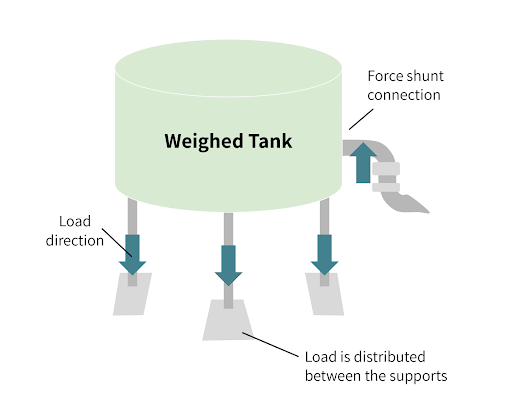
Fig 11. Weighed Vessel with Force Shunt
How can troubleshoot when having Compatibility Issues?
When encountering compatibility issues with a load cell, where the load cell may not be compatible with the measuring instrument or data acquisition system, you can take the following steps to troubleshoot the problem:
- Verify compatibility requirements: Review the specifications and documentation of both the load cell and the measuring instrument or data acquisition system. Ensure that they are compatible in terms of electrical signals, communication protocols, output format, and voltage levels. Pay attention to any specific requirements or compatibility recommendations provided by the manufacturers.
- Check electrical connections: Verify that the electrical connections between the load cell and the measuring instrument or data acquisition system are properly made. Ensure that the wiring is correct, and the signal wires are connected to the appropriate input channels. Check for loose or damaged connections that may cause signal loss or interference.
- Confirm voltage and signal levels: Ensure that the voltage levels and signal ranges of the load cell match the input requirements of the measuring instrument or data acquisition system. Verify that the load cell's output signals (analog or digital) are compatible with the input channels of the measuring instrument. Use appropriate signal conditioning devices or converters if necessary to match the signal levels.
- Evaluate communication protocols: If the load cell and measuring instrument rely on a specific communication protocol (e.g., RS-232, RS-485, Modbus), ensure that both devices support the same protocol. Check the settings, baud rates, and data formats to ensure compatibility. Make necessary adjustments or consider using protocol converters if the devices use incompatible protocols.
- Update firmware or software: Ensure that the firmware or software of the measuring instrument or data acquisition system is up to date. Manufacturers often release updates to address compatibility issues or enhance compatibility with specific load cell models. Check the manufacturer's website or contact their support for any available updates.
- Consider signal conditioning: If the load cell's signal requires conditioning or amplification, use appropriate signal conditioning devices or amplifiers. Signal conditioning devices can help adjust the signal levels, filter out noise, or convert the signal format to ensure compatibility with the measuring instrument.
- Consult the load cell and instrument manufacturers: If compatibility issues persist, contact the load cell and instrument manufacturers or their technical support teams. Provide them with detailed information about the devices, the specific compatibility issues you are facing, and any troubleshooting steps you have already taken. They can provide specific guidance, recommend compatible solutions, or suggest alternative approaches.
By ensuring compatibility between the load cell and the measuring instrument or data acquisition system, you can ensure accurate and reliable data acquisition. Reviewing specifications, verifying connections, addressing signal levels, and seeking manufacturer support are essential steps in troubleshooting compatibility issues.
How can troubleshoot Wiring and Connection Problems?
When troubleshooting wiring and connection problems with a load cell, you can take the following steps:
- Inspect the wiring: Start by visually inspecting the wiring connections between the load cell, signal conditioning equipment (if applicable), and the measuring instrument or data acquisition system. Look for loose, damaged, or improperly connected wires. Check for any exposed or frayed wires that may cause short circuits or signal interference.
- Ensure proper wire connections: Verify that the load cell's signal wires are connected to the correct terminals or channels on the signal conditioning equipment or measuring instrument. Consult the documentation or wiring diagrams provided by the load cell and instrument manufacturers for the correct wiring configuration.
- Check for continuity: Use a multimeter set to the continuity test mode to check the continuity of the wires. With the load cell disconnected from power, touch the multimeter probes to each end of the wires. Ensure that there is continuity, indicating that the wires are not broken or disconnected. If there is no continuity, inspect the wire connections and repair or replace any faulty wires.
- Test the cable: If the load cell is connected to the measuring instrument or data acquisition system using a cable, inspect the cable for any visible damage or breaks. Perform a continuity test on the cable using a multimeter to ensure that the conductors are intact. Replace the cable if necessary.
- Verify cable integrity: Check for cable integrity by gently moving or flexing the cables while observing the load cell's readings. If there are fluctuations or intermittent connections, it may indicate a problem with the cable. Try wiggling the connectors and cables to identify any loose connections or faulty components.
- Ensure proper grounding: Verify that the load cell and all connected equipment are properly grounded. Grounding helps to minimize electrical noise and interference. Ensure that the load cell's grounding terminal is connected to a reliable and dedicated ground point. Follow the grounding recommendations provided by the load cell and instrument manufacturers.
- Consider using shielded cables: If electrical noise or interference is suspected, replace the cables with shielded cables. Shielded cables help minimize the impact of external electromagnetic interference on the load cell's signal. Ensure that the shields are properly grounded at both ends.
- Inspect connectors: Examine the connectors at each end of the cables for any damage, dirt, or corrosion. Clean the connectors if necessary and ensure they are securely connected to their respective ports. Replace any damaged connectors or cables as needed.
- Perform a system check: Verify the overall system functionality by applying a known load or performing a calibration test. Monitor the load cell readings and compare them to expected values. If the readings are inconsistent or significantly deviate, double-check the wiring connections and troubleshoot further if needed.
- Consult the load cell and instrument manufacturers: If the wiring and connection problems persist or if you are unsure about the correct wiring setup, contact the load cell and instrument manufacturers or their technical support teams. Provide them with detailed information about the problem and any troubleshooting steps you have already taken. They can provide specific guidance, recommend solutions, or assist in resolving any wiring-related issues.
By thoroughly inspecting the wiring, ensuring proper connections, and addressing any cable or connector issues, you can troubleshoot wiring and connection problems with a load cell effectively.
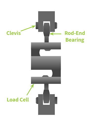
Fig 12. S-Beam Load Cell Mounted to Rod End and Clevis Assembly
TEST PROCEDURES AND ANALYSIS
A quick diagnostic check of a load cell is relatively simple. The process is straightforward, and only a few pieces of equipment are necessary. If the load cell is found at fault, the device should be returned to the manufacturer for more evaluation and essential repairs. An ohmmeter can be used for many of the checks. Isolate the location of the problem by passing a moderately light deadweight over each load cell or by disconnecting each load cell.
TEST 1: ZERO BALANCE
The load cell's output under "no-load" conditions is referred to as the zero balance. Therefore, removing all weight (even dead load) from the load cell is necessary. Low-capacity load cells should be tested in the place where the load cell is designed to measure force to avoid the weight of the element generating incorrect results.
Load cells with a low capacity should be measured where they are meant to measure force so that the element's weight doesn't provide inaccurate results. A steady power source should be used to power the load cell; ideally, this is a load cell indicator with an excitation voltage of at least 10 volts. If you have more than one load cell, disconnect the other ones. Calculate the Zero Balance in mV/V using a millivoltmeter to measure the voltage across the load cell's output leads, then divide the result by the input or excitation voltage. Check the Zero balance against the data sheet or original load cell calibration certificate.
ANALYSIS
If the load cell has been irreversibly damaged by overloading or excessive shocks, changes in Zero Balance typically happen. The strain gauge resistance is most likely changing in load cells that endure progressive zero output changes over time due to chemical or moisture intrusion. But this will also lead to a decrease in insulation resistance and a breakdown in the bridge's structural integrity.
TEST 2: INSULATION RESISTANCE
The load cell circuit and element or cable shield are used to test the insulation resistance. After removing the load cell from the junction box or indicator, you should connect the input, output, and sense (if applicable) leads together. Use a megohmmeter to measure the insulating resistance between these four to six connected leads and the load cell body. Repeat the test between the same four or six leads and the cable shield. Finally, check the insulation resistance between the cable shield and the body of the load cell.
A megohmmeter should never be used to measure input or output resistance because it typically runs at voltages far higher than the maximum excitation voltage!
Please disregard the housing and screen insulation tests if the shield is connected to the load cell body.
ANALYSIS
All load cells should have insulation resistance of 5000 megohms or more between the load cell body and cable screen, the bridge circuit to the housing, and the bridge circuit to the cable screen.
A lower value means electrical leakage, typically due to moisture or chemical contamination within the load cell or cable. Extremely low values (1k) mean that there is a short circuit instead of moisture ingress. Electrical leakage typically produces unsteady output from load cells or scales. The temperature may affect the stability.
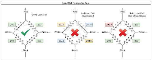
Fig 13. load cell resistance test
TEST 3: BRIDGE INTEGRITY
The input and output resistances, and the bridge balance, are measured to ensure the bridge's integrity. Remove the load cell's connection to the junction box or measuring instruments. An ohmmeter measures the input and output resistance across each pair of input and output leads. Check the input and output resistance about the specifications on the datasheet or the original calibration certificate if available. Comparing the resistance from -output to -input and -output to +input yields the bridge balance. The difference between the two values ought to be ≤ 1Ω.
ANALYSIS
The most frequent reasons for changes in bridge resistance or balance include burned or damaged wires, failed electrical components, and internal short circuits. This could happen due to excessive voltage (from lightning or welding), physical damage from shock, vibration, fatigue, or high temperatures.
TEST 4: SHOCK RESISTANCE
The load cell needs to be connected to a steady power source; ideally, this is a load cell indicator with an excitation voltage of at least 10 volts. For systems with multiple load cells, disconnect all other load cells. Using a small mallet, lightly hit the load cell to shock it while a voltmeter is connected to the output leads. Carefully avoid overloading low-capacity load cells when testing their shock resistance. During the test, pay attention to the readings. The readings should not deviate from their initial zero readings, become erratic, and should remain generally stable.
ANALYSIS
Unstable readings caused by an electrical transient may suggest a broken electrical connection or a damaged glue layer between the strain gauge and the element.
Conclusion
In conclusion, troubleshooting load cell issues is crucial for ensuring accurate and reliable measurements. Throughout this research, we have explored various common problems that can affect load cells, including overloading, non-linearity, temperature effects, creep, hysteresis, electrical noise, compatibility issues, and wiring problems.
By understanding the underlying causes of these issues and implementing appropriate troubleshooting techniques, operators can overcome challenges and optimize the performance of load cells. Regular calibration, an inspection of mounting and installation, environmental considerations, and attention to wiring connections are all vital aspects of load cell troubleshooting.
Additionally, seeking guidance from load cell manufacturers or professional technicians can provide valuable insights and specific recommendations tailored to the particular load cell system. By taking a systematic approach to troubleshooting and addressing potential problems, users can maintain the accuracy, reliability, and longevity of load cells.
Load cells play a pivotal role in numerous industries, contributing to efficient and precise weight and force measurements. By ensuring their proper functioning through effective troubleshooting, we can continue to rely on load cells as essential tools in a wide range of applications.
References
https://www.encardio.com/blog/load-cells-types-how-it-works-applications-advantages
https://ars.els-cdn.com/content/image/1-s2.0-S1350630718305521-gr1.jpg
https://harvestimaging.com/blog/?p=1125
https://www.twi-global.com/images/00015/9801.gif
https://byjus.com/jee/hysteresis/
https://tacunasystems.com/knowledge-base/reducing-noise-in-very-sensitive-load-cell-applications/
https://tacunasystems.com/knowledge-base/load-cell-mounting-and-installation-best-practices/
https://www.anyload.com/load-cell-troubleshooting-guide/
Recent Posts
-

Booster Pump Troubleshooting and Maintenance: How to Fix and Prevent Common Issues
1. Introduction Imagine turning on your faucet only to be greeted with a weak trickle of water when …22nd Apr 2025 -

Energy-Efficient Booster Pumps: Selection and Tips for Maximizing Performance
1. Introduction Imagine never having to deal with fluctuating water pressure, noisy pumps, or skyroc …19th Apr 2025 -

Booster Pumps for Sustainable Water Systems: Irrigation and Rainwater Harvesting Solutions
1. Introduction Water scarcity is no longer a distant threat—it’s a reality affecting millions …16th Apr 2025