

Installation of Flow Meters
Installation of flow meters is an important matter, so much so that the wrong installation can harm the flow meters' measurement accuracy.
The following listing suggests several details that an engineer must take into consideration when installing a pressure-based flow meter.
Configuration of piping system
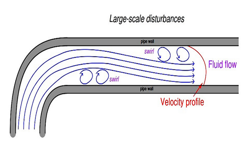
sharp turns in piping networks cause large-scale turbulence in the flow stream.
Valves, fans, Elbows, tees, and pumps are several of the most common reasons for large-scale turbulence in piping systems.
Successive pipe elbows are one of main reasons for turbulence in the system.
When such piping arrangements disturb the natural flow path of a fluid, the velocity profile of that fluid will become distorted.
Large eddies in the flow stream (known as swirl) will appear. This can create challenges for pressure-based flow meters which depend on linear acceleration to measure the fluid flow rate.
That’s why pressure-based flow meters ought to be positioned upstream and away from essential disturbance causing devices like control valves and pipe elbows wherein possible.
Even disturbance creating devices placed downstream of the flow element can have an impact on measurement accuracy.
We should devise approaches for stabilizing a flow stream’s velocity profile close to the flow element to gain precise measurements of flow rate.
A quite effective and simple way to do this is to provide sufficient length of straight pipe ahead of (and behind) the flow element.
Recommendations for minimal upstream and downstream straight-pipe lengths vary highly with the character of the turbulent, piping geometry, and flow element.
As a standard rule, smaller beta ratio (ratio of throat diameter d to pipe diameter D) are more tolerant of disturbances, with profiled flow tools (for example venturi tubes, flow tubes, V-cones) having the highest tolerance.
You'd better seek advice from the flow element producer's documentation for more specific advice suitable to any specific application.
Instruments referred to as flow conditioners can be installed upstream of the flow element to assist the flow profile gain symmetry in a much shorter distance than a simple straight pipe could do alone.
They stabilize the flow stream before coming into a flow element:
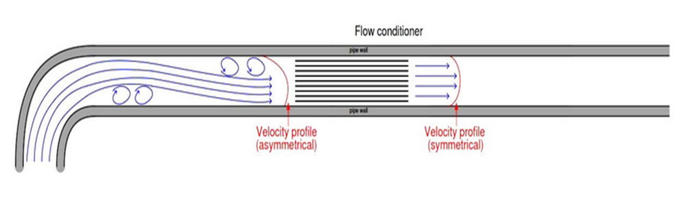
however, the use of low-beta factors can also increase permanent pressure loss causing energy loss.
Placing of the flow meter in application
In applications wherein accuracy is crucial, flowmeter position should be a priority although it means a more expensive and unattractive piping design.
Another common source of trouble for pressure-based flowmeters is inappropriate transmitter location.
Here, the type of fluid being calculated dictates how the pressure-sensing device should be positioned in relation to the pipe.
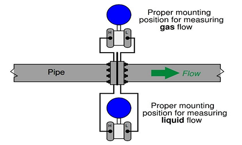
For gas and vapor flows, no stray liquid droplets must gather within the impulse lines.
For liquid flows, no gas bubbles must gather in the impulse lines.
To allow gravity to prevent these challenges, operators should locate the transmitter below the pipe for liquid flow applications and above the pipe for gas flow applications.
This example shows each installation for a horizontal pipe:
the next example shows both installations on a vertical pipe:
Vapor applications (including measurement of steam flow) have been traditionally dealt with similarly to liquid measurement applications.
In this case, the condensed liquid will gather in the transmitter’s impulse lines so and causes the impulse lines to be cooler than the vapor flowing thru the pipe (which is normally the case).
Locating the transmitter under the pipe lets in vapors to condense and fill the impulse lines with liquid (condensate), which then acts as a natural seal inhibiting the transmitter from being exposed to hot process vapors.
In such applications, it is critical that the technician pre-fills both impulse lines with condensed liquid before placing the flowmeter into service.
“Tee” fittings with detachable plugs or fill valves are designed to do this. Failure to pre-fill the impulse lines will probably bring about measurement mistakes throughout the preliminary operation, as condensed vapors will necessarily fill the impulse lines at barely different rates and cause a difference in the vertical liquid column heights within those lines.
Important note: some steam flow element installations will operate well if the impulse lines are above the pipe.
If such an installation is possible, not having to address pre-filling impulse lines (or looking forward to steam condensing to equal levels in both lines) is highly advantageous.
If tap holes need to be drilled into the pipe (or flanges) at the process site, high care should be taken to account to drill properly and smooth the rough edges of the holes.
Also, there have to be no reliefs or countersinking close to the hole on the inside of the pipe. Even small irregularities at the tap holes can generate significantly large errors in flow-measurement.
In short you should take the following steps into consideration when installing flow measuring device:
Flow Meter Installation Case Study
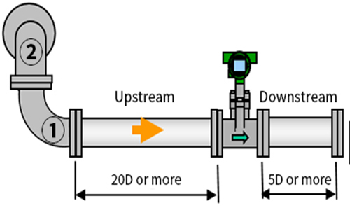
Here we would like to study a case of an orifice plate installation, wherein the straight-run pipe requirement had been ignored:
As shown above Not only is the orifice plate installed too close to an elbow, the elbow is located at the upstream side of the orifice plate, wherein disturbances usually happen!
The orifice plate should have been placed alongside the piping lengths and not too close to the elbow.
Unfortunately, Poor installations like this are significantly routine.
Of all the standards which have to be taken into account whilst designing a piping layout, the flowmeter location is regularly located low in the order of importance (if it is located at all!).
What are "downstream" and "upstream" in fluid dynamics?
Upstream is away from the endpoint i.e. going upward whilst Downstream is the flow of fluid closer to the endpoint of a pipe you consider.
Orifice Flow Meter Rangeability
Orifice, combined with a differential pressure transmitter, is the most commonly used flow measurement instrument in the oil & gas industry due to its low cost and simplicity of set up and maintenance.
However, orifice just permits 3:1 rangeability to keep accuracy, i.e. if someone intends to calculate a maximum flow of 10 MMscfd, then the minimum flow calculation that could be measured will be merely 3.3 MMscfd.
According to Bernoulli principle, the relationship between flow and pressure drop of fluid passing through an orifice is given by the subsequent formula:
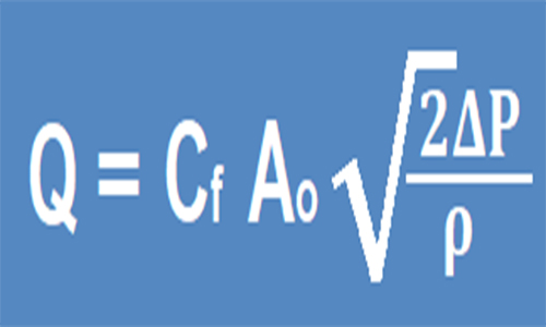
Q = volumetric flow rate
dP = calculated pressure drop ρ = flow rate
Ao = cross-sectional orifice area
Cf = constant
So, flow value can be gained via measuring pressure drop and the relationship between them is a square root.
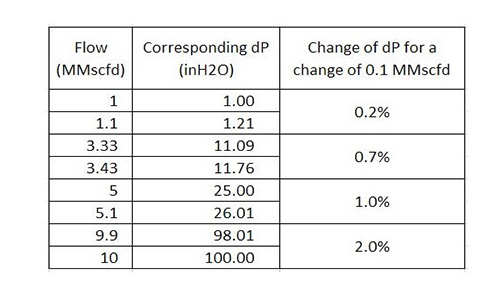
Let’s say the orifice is meant for flow measurement of 0 to 10 MMscfd which is represented by 0 to 100 inH2O pressure drop (as indicated below)

A maximum flow of 10 MMscfd, a change of 1% of full flow (0.1 MMscfd) to 9.9 MMscfd can be represented by a change of 2% of dP (from 100 inH2O to 98.01 in H2O).
The following table summarized the value of flow, its corresponding pressure drop, and its dP change in percentage of full scale for a 1% change of full flow at the specified flow.
The less flow to be measured, the greater sensitivity suffers.
Recent Posts
-

Booster Pump Troubleshooting and Maintenance: How to Fix and Prevent Common Issues
1. Introduction Imagine turning on your faucet only to be greeted with a weak trickle of water when …22nd Apr 2025 -

Energy-Efficient Booster Pumps: Selection and Tips for Maximizing Performance
1. Introduction Imagine never having to deal with fluctuating water pressure, noisy pumps, or skyroc …19th Apr 2025 -

Booster Pumps for Sustainable Water Systems: Irrigation and Rainwater Harvesting Solutions
1. Introduction Water scarcity is no longer a distant threat—it’s a reality affecting millions …16th Apr 2025