

Getting Started With Load Cell
Do you ever wonder how industries accurately measure the forces that shape our world? From weighing massive cargo containers to ensuring the structural integrity of bridges, the answer lies in a small but mighty device known as the load cell. With its ability to transform mechanical force into precise electrical signals, the load cell plays a vital role in industries ranging from manufacturing to aerospace. Join me as we delve into the fascinating world of load cells and uncover the remarkable science behind their incredible power to measure and control forces with unwavering accuracy.
What is a load cell?
A load cell is a transducer or sensor used to measure force or weight. It converts a mechanical force into an electrical signal that can be measured and analyzed. Load cells are commonly used in various industries and applications where precise force or weight measurement is required.
Load cells typically consist of a metal structure or body with strain gauges attached to it. When a force or load is applied to the load cell, the strain gauges change their electrical resistance in proportion to the applied force. This change in resistance is then converted into an electrical signal, usually in the form of voltage, which can be measured by a connected device such as a digital display, data logger, or control system.
Load cells are available in different types and configurations to suit specific applications. Some common types include:
- Compression Load Cell: Designed to measure forces along a single axis, usually by compressing the load cell.
- Tension Load Cell: Used to measure forces in tension or pulling applications, where the load is applied in a straight line.
- Shear Load Cell: Designed to measure forces in shear or lateral applications, where the load is applied parallel to the sensor.
- Bending Beam Load Cell: Consists of a beam that bends under load, and the strain gauges measure the deformation to determine the applied force.
Load cells find applications in various industries such as manufacturing, aerospace, automotive, healthcare, robotics, and many more. They are used in weighing scales, material testing machines, industrial automation systems, force measurement equipment, and other devices where accurate force or weight measurement is crucial.
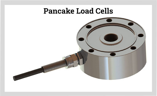
Fig 1. A Pancake load cell
What is the history of the load cell?
The concept of load measurement and force sensing dates back many centuries, but load cells as we know them today have a more recent history. Here's a brief overview of the development and history of load cells:
- Early Developments: The earliest load measurement devices can be traced back to ancient civilizations, where basic lever systems and spring balances were used to measure weight and force. These early systems relied on mechanical principles and did not have the advanced electronic components found in modern load cells.
- Strain Gauge Invention: The development of strain gauges in the mid-20th century played a crucial role in the evolution of load cells. In 1938, Edward E. Simmons and Arthur C. Ruge invented the bonded resistance strain gauge, which could measure minute changes in electrical resistance when subjected to mechanical strain. This invention laid the foundation for load cell technology.
- First Load Cells: In the 1940s, load cells began to emerge as practical devices for force measurement. The pioneering work of Arthur C. Ruge at the Massachusetts Institute of Technology (MIT) led to the development of the first practical load cells. These early load cells utilized strain gauges bonded to metallic elements and were primarily used in laboratory and research settings.
- Strain Gauge Load Cells: During the 1950s and 1960s, load cell technology advanced further with the introduction of strain gauge load cells. These load cells used multiple strain gauges arranged in a Wheatstone bridge configuration to improve accuracy and sensitivity. They became more widely used in industrial applications due to their reliability and improved performance.
- Digital Load Cells: In the 1980s and 1990s, load cells transitioned from analog to digital technology. Digital load cells integrated microprocessors and digital signal processing capabilities, allowing for more advanced features such as calibration, temperature compensation, and communication interfaces. This digital revolution improved accuracy, reliability, and ease of integration with computerized systems.
- Advancements and Diversification: Load cell technology has continued to evolve with advancements in materials, electronics, and manufacturing techniques. Load cells now come in various designs, sizes, and capacities to suit different applications, including miniature load cells for precision measurements and high-capacity load cells for heavy-duty industrial applications.
Today, load cells are widely used in diverse industries, enabling precise and reliable force and weight measurements in a wide range of applications, from industrial automation and weighing scales to aerospace and healthcare. The ongoing advancements in load cell technology continue to enhance their performance, accuracy, and capabilities.
How is a load cell structure?
A load cell typically consists of several key components that work together to measure force and convert it into an electrical signal. While there are different types and designs of load cells, the following components are commonly found in load cell structures:
- Load-Bearing Structure: The load-bearing structure is the main body of the load cell that supports the load or force to be measured. It is usually made of durable and rigid material, such as stainless steel or aluminum, to ensure strength and stability.
- Strain Gauges: Strain gauges are vital components of load cells. They are bonded to the load-bearing structure and undergo deformation when the load is applied. Strain gauges are made of thin metallic foils that exhibit changes in electrical resistance when subjected to mechanical strain. The strain gauges are arranged in a Wheatstone bridge configuration to accurately measure the deformation caused by the applied force.
- Wiring: Load cells have electrical wiring connecting the strain gauges to the external circuitry. The strain gauge wires are typically thin and delicate, requiring careful handling and protection to prevent damage.
- Insulating Materials: Insulating materials are used to protect the strain gauges and wiring from external factors such as moisture, dust, and electrical interference. These materials help maintain the integrity of the electrical signals generated by the strain gauges.
- Mounting Hardware: Load cells may include mounting hardware, such as threaded holes or mounting brackets, to facilitate their installation and integration into various systems or equipment.
- Output Connector: Load cells have an output connector that allows the electrical signal to be transmitted to external devices. The connector can be in the form of wires, pins, or other types of connectors depending on the load cell design and application.
Additionally, depending on the type of load cell, there may be additional components such as mechanical stops, overload protection devices, and protective coatings to enhance the load cell's performance and durability.
It's important to note that load cell structures may vary based on their specific design, capacity, and intended application. Manufacturers often customize load cells to meet the requirements of different industries and applications while maintaining the fundamental principles of force measurement using strain gauges.
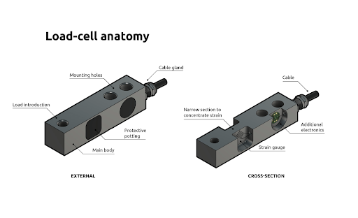
Fig 2. Load cell anatomy
What are the load cell's internal components?
Load cells typically consist of several internal components that work together to measure force and convert it into an electrical signal. The specific internal components can vary depending on the design and type of load cell, but here are the key components commonly found in load cells:
- Strain Gauges: Strain gauges are the primary sensing elements in a load cell. These thin metallic foils are bonded to the load-bearing structure and undergo deformation when a force is applied. The strain gauges are wired in a Wheatstone bridge configuration to accurately measure the changes in electrical resistance caused by the strain.
- Wheatstone Bridge: The Wheatstone Bridge is an electrical circuit configuration that consists of four strain gauges. It balances and measures the changes in electrical resistance of the strain gauges when a force is applied. The output voltage of the Wheatstone bridge is proportional to the applied force.
- Analog-to-Digital Converter (ADC): In load cells with digital output, an ADC is used to convert the analog voltage signal from the Wheatstone bridge into a digital signal that can be processed by external devices or systems. The ADC provides digital output values that represent the measured force or weight.
- Amplifier/Signal Conditioning Circuit: Load cells often include an amplifier or signal conditioning circuitry. This circuit amplifies the weak electrical signal from the Wheatstone bridge, increases its stability, and filters out unwanted noise or interference. The amplifier or signal conditioning circuit ensures that the output signal is accurate and reliable.
- Excitation Circuit: The excitation circuit provides a stable and regulated electrical voltage or current to the strain gauges. It is responsible for energizing the strain gauges and maintaining a consistent power supply to ensure accurate measurements.
- Cables and Wiring: Load cells have internal cables and wiring connections that link the strain gauges, Wheatstone bridge, and other components together. These cables transmit the electrical signals within the load cell and are designed to minimize interference and maintain signal integrity.
- Housing/Enclosure: Load cells are typically housed in a protective enclosure or housing. This provides physical protection to the internal components, shields them from environmental factors, and ensures the load cell's durability and longevity.
It's worth noting that load cell designs may vary, and some load cells may incorporate additional components such as temperature compensation devices, calibration circuits, and overload protection mechanisms. The specific internal components can differ based on the load cell's capacity, accuracy requirements, and intended application.
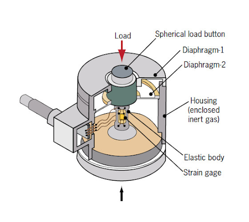
Fig 3. A typical load cell
Technology Of A Load Cell
Most load cells have two parts:
- The main body of the sensor
- An attached electrical circuit
The main body, which makes up the majority of the load cell's size, is what endures the weight or force. It is often made of high-quality steel or aluminum, which makes it mechanically reliable and ensures predictable and uniform strain distribution.
The electrical circuit is inside the load cell and is firmly attached to the main body. The circuit contains strain gauges, which are specialized circuit components intended to detect deformations in the main body.
Strain gauges are thin, electrically conducting wires or foil organized in a zig-zag pattern. This design makes them stretch and compression-sensitive throughout their length but insensitive across their width. As a result, they can be placed precisely to detect forces along specific axes. For instance, shear beam load cells include strain gauges angled 45 degrees to the loading axis to maximize shear strain detection running via the load cell.
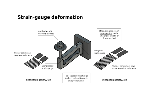
Fig 4. The technology of a load cell
How does the load cell work?
Load cells work based on the principle of converting mechanical force or weight into an electrical signal. Here's a step-by-step explanation of how a load cell typically works:
- Application of Force: When a load or force is applied to a load cell, it exerts a mechanical strain on the load-bearing structure of the load cell. This strain causes the load-bearing structure to deform slightly.
- Deformation and Strain Gauges: The deformation of the load-bearing structure causes a proportional strain on the strain gauges attached to it. Strain gauges are thin metallic foils that change their electrical resistance when subjected to mechanical strain. The strain gauges are strategically positioned on the load cell to measure the strain resulting from the applied force.
- Wheatstone Bridge Configuration: The strain gauges are arranged in a Wheatstone bridge configuration, which consists of four strain gauges connected in a specific pattern. The Wheatstone bridge configuration allows for accurate measurement of the strain and helps compensate for temperature variations and other external factors.
- Change in Resistance: As the load cell deforms under the applied force, the strain gauges experience changes in their electrical resistance. The strain gauges in tension (stretched) experience an increase in resistance, while the strain gauges in compression (compressed) experience a decrease in resistance.
- Electrical Output: The change in resistance of the strain gauges results in unbalanced voltage output from the Wheatstone bridge. This voltage output is directly proportional to the applied force or weight. The electrical output is usually in the form of a small electrical signal, typically in millivolts (mV).
- Amplification and Conditioning: The small electrical signal from the Wheatstone bridge is amplified and conditioned by an amplifier or signal conditioning circuitry. The amplifier increases the signal strength, improves its stability, and filters out any unwanted noise or interference.
- Output Conversion: In digital load cells, the amplified electrical signal is converted from analog to digital using an Analog-to-Digital Converter (ADC). The ADC converts the analog voltage signal into digital values that represent the measured force or weight.
- Output Transmission: The final electrical signal, whether analog or digital, is transmitted to external devices or systems for further processing, display, or control. This can be done through wiring connections, communication interfaces, or wireless transmission, depending on the load cell design and application.
By accurately measuring the changes in electrical resistance of the strain gauges, load cells provide a precise and reliable measurement of force or weight. The electrical signal output can be calibrated and calibrated to represent the applied force or weight in various units, making load cells widely used in numerous industries and applications where force measurement is critical.
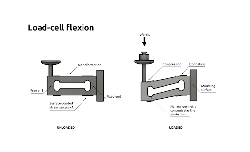
Fig 5. The load cell working principle
Does a load cell have any formula?
A load cell itself does not have a specific formula associated with it. Load cells are transducers that convert applied force or weight into an electrical signal, typically a change in resistance or voltage. The output of a load cell is generally proportional to the applied load, following a specific relationship determined by its design and characteristics.
Load cells are often characterized by their sensitivity, which is the ratio of the change in output to the change in applied load. This sensitivity is usually provided by the manufacturer as a specification and is typically expressed in units of millivolts per volt (mV/V) or volts per volt (V/V) per unit of applied load.
To obtain the actual force or weight measurement from the load cell output, you may need to consider additional factors such as calibration, signal conditioning, and calibration curves. These factors can vary depending on the load cell model, manufacturer, and application.
In some cases, load cell outputs can be linearly correlated to the applied load, allowing for straightforward conversion. For example, if a load cell has a sensitivity of 2 mV/V and a full-scale output of 10 volts, a change of 1 volt in the output corresponds to a 500 kg (kilogram) change in the applied load.
However, it's important to note that load cells may exhibit non-linear characteristics, hysteresis, or temperature effects that can affect the relationship between the load cell output and the applied load. To ensure accurate measurements, load cells are often calibrated using known reference weights or standards, and calibration curves are generated to establish the relationship between the load cell output and the applied load.
The specific formula or conversion equation to obtain force or weight from the load cell output can depend on various factors, including the load cell's characteristics, calibration procedure, and the calibration curve established for that particular load cell.
Therefore, it is recommended to refer to the load cell manufacturer's documentation, calibration procedures, and any specific instructions or equations provided by them to accurately convert load cell output to force or weight measurements for your particular load cell model.
Environmental Protection
A load cell can be employed in various environmental conditions based on the setting. A clean room in a medical lab and the underbelly of an open-cast mining truck are pretty different, and both require various types of load cells. So, protecting them from the outside environment is essential to maintain their long-term performance for their intended application. The majority of load cells are potted. This means that the voids are filled with an epoxy-or resin-based substance that completely covers the electrical components. This protects the circuits from external damage and humidity and also aids in heat dissipation.
Hermetic sealing is available on some load cells to provide the best environmental protection. A wholly welded seal creates an airtight, durable enclosure that can withstand the harshest conditions.
Some load cells come with ATEX and FM certifications. These certifications demonstrate that the product is suitable for use in potentially explosive settings without the danger of sparking. This is appropriate for operations that create flammable gases or vapors, such as spraying car paint, or workplaces that deal with fine organic dust, like grain flour or wood.
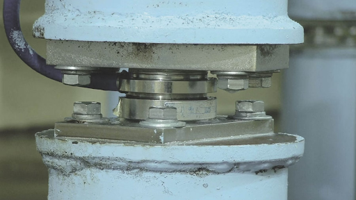
Fig 6. Load cells in the industry
What is the purpose of a load cell?
The purpose of a load cell is to accurately measure force or weight and convert it into an electrical signal that can be processed, analyzed, or used for control purposes. Load cells are designed to provide precise and reliable force measurements in a wide range of applications. Here are the main purposes or objectives of using a load cell:
- Force Measurement: Load cells are primarily used to measure forces in different applications. They provide accurate and quantitative measurements of forces or weights applied to the load-bearing structure of the load cell.
- Weight Measurement: Load cells are commonly used for weight measurement purposes. They enable the precise determination of the weight of objects, materials, or components.
- Control and Feedback: Load cells provide real-time feedback about the applied force or weight. This information can be utilized to control systems or processes. Load cells can be integrated into control systems to ensure that specific force or weight limits are not exceeded, enabling safe and reliable operation.
- Monitoring and Data Collection: Load cells allow for continuous or periodic monitoring of forces or weights. This data can be collected and analyzed to gain insights into performance, efficiency, or structural integrity. Load cells help in quality control, process optimization, and equipment maintenance.
- Safety and Load Limiting: Load cells play a crucial role in safety applications. They can be used to monitor loads and ensure that they do not exceed safe limits. This is particularly important in lifting equipment, cranes, and other load-bearing structures where overloading can lead to accidents or structural failures.
- Process Optimization: Load cells are employed in various industries to optimize processes. By accurately measuring forces or weights, load cells assist in optimizing material usage, determining appropriate load distribution, and ensuring precise positioning or alignment.
- Research and Development: Load cells are essential tools in research and development activities. They enable scientists and engineers to conduct experiments, gather data, and measure forces accurately for analysis and validation of theories, designs, and prototypes.
Overall, the purpose of a load cell is to provide accurate force or weight measurements, enabling better control, monitoring, safety, and optimization in various applications across industries.
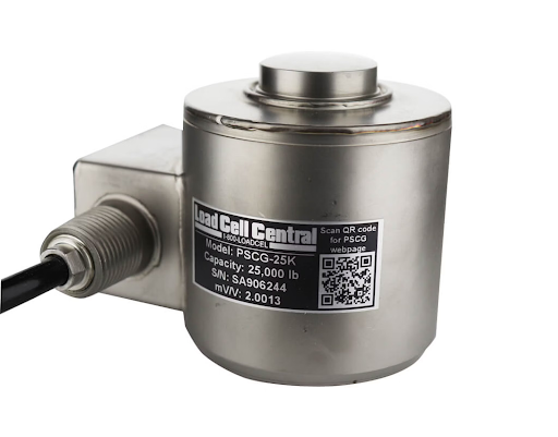
Fig 7. An example of a load cell
Installation and maintenance
How to use a load cell in a circuit?
To use a load cell in a circuit, you need to consider the electrical characteristics of the load cell and how it interfaces with other components. Here are the general steps involved in using a load cell in a circuit:
- Power Supply: Load cells require a stable power supply to operate. Determine the voltage and current requirements specified by the load cell manufacturer. Make sure to provide the load cell with the appropriate power supply within the specified range.
- Wheatstone Bridge: Load cells typically employ a Wheatstone bridge configuration to measure the change in resistance caused by the applied force. The strain gauges within the load cell are connected in a Wheatstone bridge pattern. Connect the load cell's strain gauge terminals to the appropriate pins of the Wheatstone bridge circuit.
- Signal Amplification and Conditioning: The electrical signal generated by the load cell is usually small and requires amplification and conditioning for further processing. Use an amplifier or signal conditioning circuitry to boost the load cell's output signal and remove any unwanted noise or interference.
- Output Conversion: Depending on the application, you may need to convert the analog signal from the load cell to a digital format. This can be done using an Analog-to-Digital Converter (ADC). The ADC converts the analog signal to digital values for processing by microcontrollers, computers, or other digital devices.
- Calibration: Load cells may require calibration to ensure accurate measurements. Follow the manufacturer's guidelines to calibrate the load cell, adjusting the output signal based on known reference weights or forces.
- Output Integration: Connect the output of the load cell circuit to the intended destination, such as a display, data acquisition system, microcontroller, or control system. The specific integration will depend on the requirements of your application.
- Wiring and Connections: Pay attention to the proper wiring and connections of the load cell circuit. Ensure the correct connections between the load cell, Wheatstone bridge, amplifier, ADC, and other components. Use appropriate wiring techniques to minimize noise and interference.
It's important to note that the specific circuitry and components used may vary depending on the load cell model, application, and desired functionality. It's recommended to consult the load cell's datasheet or the manufacturer's instructions for specific details on integrating the load cell into a circuit.
Installation
The mechanical installation of an Alfa Laval load cell is very simple and easy as sideload and overload protection devices are most often not necessary since the non-contacting capacitive measuring principle allows for high overloads and sideloads. When mounting the load cell, it is placed between the force-introducing structure and the base, which ideally are two parallel surfaces.
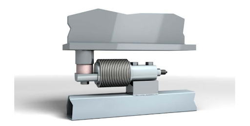
Fig 8. Mechanical installation
For the highest accuracy, please ensure that the force is applied vertically on the loading surface (load point) of the load cell. The force should not be applied to the load cell outside the loading surface (load point).
Please notice that rigid process tubing will cause errors and should be considered when designing the installation:
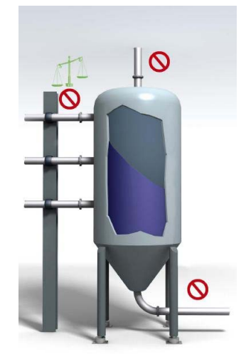
Fig 9. Installation warning
To prevent force shunts, all connections from the weighing system to the surrounding construction (pipes, cables, bellows) must be as flexible as possible.
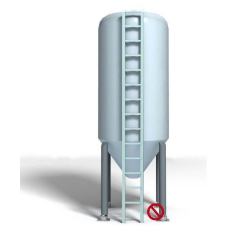
Fig 10. Load cell connection
Any component or part causing resistance to vertical movement of the load, the parts to be weighed and the load cells will induce accuracy errors. Determine if any vibration or influence on the weighing system is caused by other systems operating close by. If possible, do try to minimize the vibrations on the load cells in order to achieve the best weighing performance.
Safety tips should observe while using load cells
When using load cells, it's important to follow proper safety precautions to ensure the well-being of personnel and the correct operation of the equipment. Here are some safety tips to observe while using load cells:
- Read the Manufacturer's Instructions: Familiarize yourself with the load cell's user manual, specifications, and safety guidelines provided by the manufacturer. Follow their recommendations for installation, operation, maintenance, and any specific safety precautions.
- Use Appropriate Load Ratings: Ensure that the load cell you are using is suitable for the intended load range. Avoid exceeding the load cell's maximum rated capacity, as it can lead to inaccurate measurements, damage to the load cell, or even equipment failure.
- Correct Installation: Follow proper installation procedures for the load cell. Ensure that the load is applied centrally and evenly to the load cell's sensing element. Avoid side loads or off-center loading, as it can introduce measurement errors or damage the load cell.
- Environmental Considerations: Take into account the environmental conditions in which the load cell operates. Protect the load cell from excessive humidity, temperature extremes, corrosive substances, or vibrations that can affect its performance. Use appropriate enclosures or protective measures as needed.
- Proper Wiring and Connections: Ensure correct wiring and connections of the load cell, following the manufacturer's instructions. Use appropriate wiring techniques, such as shielding or twisted pairs, to minimize electrical noise and interference. Check the wiring for any signs of damage or wear regularly.
- Overload Protection: Implement measures to protect the load cell from excessive loads or overloading. This can include using mechanical stops, limit switches, or load limiters to prevent the load from exceeding the load cell's rated capacity.
- Regular Inspection and Maintenance: Perform regular inspections of the load cell, including the strain gauges, cables, and connectors, to ensure their integrity and proper functioning. Follow the manufacturer's recommended maintenance schedule for calibration, testing, and any necessary adjustments.
- Training and Personnel Safety: Provide appropriate training to personnel involved in the operation or maintenance of load cells. Ensure they are aware of the load cell's capabilities, limitations, and safety procedures. Use proper personal protective equipment (PPE) when required, such as gloves or safety glasses.
- Avoid Shock or Impact: Avoid subjecting the load cell to sudden shocks or impacts that can damage its components. Handle the load cell with care during installation, maintenance, or transportation.
- Follow Local Regulations: Adhere to applicable safety regulations, standards, and codes in your region or industry that govern the use of load cells.
By following these safety tips, you can minimize risks, maintain accurate measurements, and ensure the safe and reliable operation of load cells in your applications.
Does the load cell need calibration?
Yes, load cells typically require calibration to ensure accurate and reliable measurements. Calibration is the process of comparing the output of the load cell to known reference standards or weights to determine its accuracy and make necessary adjustments.
Here are a few reasons why load cell calibration is important:
- Accuracy: Over time, load cells may experience drift or changes in their electrical and mechanical properties due to various factors such as temperature fluctuations, mechanical stress, or aging. Calibration helps determine the actual output of the load cell and correct any deviations from the expected values, ensuring accurate measurements.
- Traceability: Calibration provides a documented chain of traceability for measurement results. By comparing the load cell's output to reference standards that are themselves calibrated, you can establish a traceable measurement system and have confidence in the accuracy of your measurements.
- Compliance: Many industries have specific standards, regulations, or quality management systems that require load cells to be calibrated at regular intervals. Calibration ensures compliance with these requirements and demonstrates that you are using reliable measurement equipment.
- Quality Control: Calibration is an integral part of quality control processes. By calibrating load cells, you can identify and rectify any measurement errors, reducing the risk of producing faulty or inaccurate products. Calibration helps maintain consistent and reliable measurements, improving overall product quality.
- System Performance: Load cells are often integrated into larger systems or equipment. Calibration ensures that the load cell performs optimally within the system, providing accurate data for control, monitoring, or feedback purposes. Proper calibration contributes to the overall performance and efficiency of the system.
The frequency of load cell calibration depends on various factors, including the load cell type, application, operating conditions, and industry requirements. It is recommended to refer to the load cell manufacturer's guidelines and relevant industry standards for the recommended calibration intervals.
Calibration should ideally be performed by qualified personnel using calibrated reference standards, specialized equipment, and proper procedures. This helps ensure that the calibration process itself is accurate and reliable.
By regularly calibrating load cells, you can maintain measurement accuracy, ensure compliance, and enhance the reliability of your measurement systems.
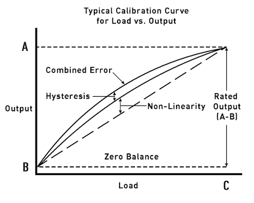
Fig 11. Typical calibration curve for load cell
How can calibrate the load cell?
Calibrating a load cell involves comparing its output to known reference standards or weights and making adjustments to ensure accurate measurements. The specific calibration procedure may vary depending on the load cell model, application, and available equipment. However, here is a general overview of the steps involved in calibrating a load cell:
- Equipment Setup: Gather the necessary equipment for calibration, including calibrated reference weights or standards, a suitable force or weight measurement device, and any required tools or accessories.
- Zeroing the Load Cell: Ensure the load cell is in a "zero" state with no applied load. This can be achieved by removing any external forces or weights and allowing the load cell to stabilize in an unloaded condition.
- Reference Weight Calibration: Place a known reference weight or standard on the load cell. Record the output reading from the load cell measurement device. Repeat this process with several different reference weights across the load cell's measurement range.
- Comparison and Adjustment: Compare the load cell's output readings to the known reference weights. Calculate the deviation or error between the load cell's readings and the expected values. If there is a systematic error or deviation, adjustments may be required.
- Adjusting the Load Cell: Depending on the load cell design, there may be adjustment mechanisms such as mechanical screws or trim pots that allow you to make fine-tuning adjustments. Follow the load cell manufacturer's instructions for making these adjustments. Ensure you use appropriate tools and techniques to avoid damage to the load cell.
- Repeating the Calibration: After making adjustments, repeat the calibration process by applying the reference weights again and comparing the load cell's output to the expected values. Continue adjusting and repeating the process until the load cell's readings align closely with the reference weights.
- Documentation: Record the calibration results, including the reference weights used, the load cell's output readings, and any adjustments made. This documentation helps establish a calibration history, traceability, and compliance with quality management systems or industry standards.
It is important to note that load cell calibration may require specialized equipment, such as force calibration machines or calibration laboratories, depending on the level of accuracy required and the specific application. If you are unsure or lack the necessary expertise, it is recommended to consult with qualified calibration technicians or professionals who can perform the calibration accurately.
Additionally, it is advisable to follow the load cell manufacturer's guidelines, specifications, and any specific calibration procedures provided by them to ensure accurate and reliable calibration results.
Load cell accuracy
The accuracy of a load cell refers to its ability to provide measurements that closely align with the true or known values. Load cell accuracy is typically expressed as a percentage of the full-scale output or as a percentage of the applied load. It represents the maximum deviation between the load cell's output and the actual force or weight being measured.
The accuracy of a load cell can be influenced by various factors, including:
- Manufacturing Tolerance: Load cells are manufactured with certain tolerances, which can affect their accuracy. Higher-quality load cells tend to have tighter manufacturing tolerances, resulting in improved accuracy.
- Linearity: Linearity refers to how closely the load cell's output follows a straight line across the full measurement range. Non-linearities can introduce measurement errors, and load cells with better linearity characteristics provide more accurate readings.
- Hysteresis: Hysteresis is the phenomenon where the output of a load cell varies depending on whether the load is increasing or decreasing. Load cells with lower hysteresis exhibit better accuracy and consistency in their readings.
- Temperature Effects: Load cell accuracy can be influenced by temperature changes. Some load cells may have temperature compensation features or be designed to minimize temperature-related errors.
- Environmental Conditions: Factors such as humidity, vibration, and electromagnetic interference can impact load cell accuracy. Load cells designed for specific environmental conditions or with appropriate shielding can help mitigate these effects.
- Calibration: Load cells require regular calibration to ensure their accuracy. Calibration adjusts the load cell's output to match known reference values, correcting any deviations or errors.
It's important to note that the accuracy of a load cell is typically specified by the manufacturer and may vary depending on the load cell model, range, and other specifications. When selecting a load cell, it is advisable to review the manufacturer's specifications and choose a load cell with the accuracy that meets the requirements of your specific application.
In addition to the load cell itself, the accuracy of the overall measurement system, including amplifiers, signal conditioning, and data acquisition devices, should also be considered to ensure accurate and reliable measurements.
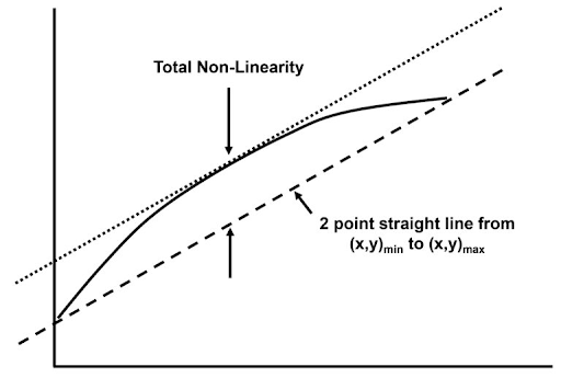
Fig 12. Non-Linearity with Baseline
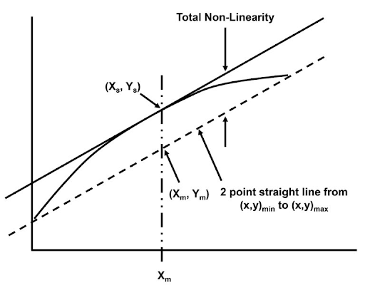
Fig 13. Midpoint Non-Linearity
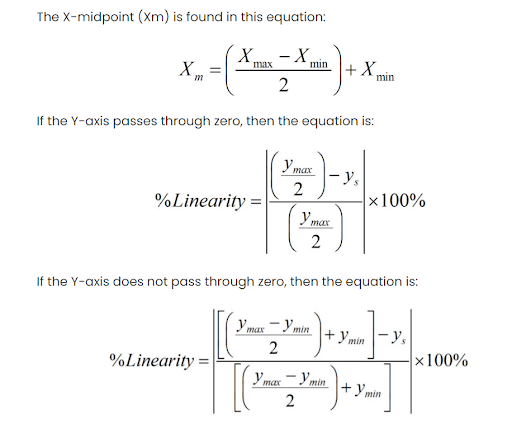
Fig 14. Linearity measurement
How to measure the accuracy?
To measure the accuracy of a load cell, you typically compare its output readings to known reference values or weights. The accuracy is then calculated as the percentage deviation or error between the load cell's readings and the expected values. Here are two common formulas used to calculate load cell accuracy:
Percentage of Full-Scale Output (%FSO):
- Accuracy (%FSO) = (Measured Output - Expected Value) / Full-Scale Output * 100%
In this formula, "Measured Output" refers to the load cell's actual output reading, "Expected Value" represents the known reference value or weight measured, and "Full-Scale Output" is the load cell's maximum rated output for the given load range. The result is expressed as a percentage of the load cell's full-scale output.
Percentage of Applied Load (%AL):
- Accuracy (%AL) = (Measured Output - Expected Value) / Applied Load * 100%
Here, "Applied Load" represents the actual force or weight being applied to the load cell. The formula calculates the accuracy as a percentage of the applied load.
It's important to note that these formulas provide a measure of the load cell's accuracy for a specific measurement point. To obtain an overall accuracy assessment, you may need to perform multiple measurements across the load cell's measurement range and calculate the average or maximum deviation.
When conducting accuracy measurements, ensure that the load cell is properly calibrated, and follow any specific procedures or guidelines provided by the load cell manufacturer. Use calibrated reference standards or weights with known accuracy to establish the expected values for comparison.
Additionally, keep in mind that the accuracy of the overall measurement system, including amplifiers, signal conditioning, and data acquisition devices, should also be considered when assessing the accuracy of load cell measurements.
Consulting the load cell manufacturer's documentation and specifications is essential for understanding the specific accuracy requirements, measurement range, and recommended procedures for evaluating the load cell's accuracy.
load cell precision
Load cell precision refers to the level of repeatability and consistency in its measurements. It indicates how closely the load cell can reproduce the same output readings for the same applied load under similar conditions. Higher precision implies lower variability and better repeatability in the load cell's measurements.
Load cell precision is typically expressed as a percentage of the full-scale output or as a percentage of the applied load. A load cell with high precision will provide consistent and repeatable measurements, even when the applied load is repeatedly applied and removed.
Factors that can influence load cell precision include:
- Manufacturing Quality: Load cells manufactured with high-quality materials, precise machining, and stringent quality control processes tend to exhibit better precision.
- Linearity: Load cells with good linearity characteristics, meaning their output follows a straight line across the measurement range, tend to have higher precision.
- Hysteresis: Load cells with low hysteresis, where the output does not vary significantly between loading and unloading cycles, tend to offer better precision.
- Stability: Load cells that are stable over time and resistant to environmental factors such as temperature changes or humidity variations tend to have better precision.
- Calibration: Regular calibration of the load cell ensures that any drift or changes in its output are corrected, enhancing precision.
It's important to note that precision and accuracy are related but distinct concepts. Precision refers to the consistency and repeatability of measurements, while accuracy relates to how close the measurements are to the true or known values. A load cell can be precise (reproducible) but not necessarily accurate (deviating from the true value), and vice versa.
To assess the precision of a load cell, multiple measurements of the same load should be taken under similar conditions, and the variability or standard deviation of the readings can be calculated. The lower the standard deviation, the higher the precision.
When selecting a load cell, consider the required precision based on your application's needs. This may depend on factors such as the desired measurement resolution, the level of precision required for your process or experiment, and any industry or regulatory standards that specify precision requirements.
Consulting the load cell manufacturer's specifications, documentation, and technical support can provide valuable insights into the precision capabilities of the load cell model you are considering.
References
https://www.flintec.com/weight-sensors/load-cells/what-is-a-load-cell
https://www.iqsdirectory.com/articles/load-cell/types-of-load-cells.html
https://learn.sparkfun.com/tutorials/getting-started-with-load-cells/all
https://tacunasystems.com/knowledge-base/load-cell-mounting-and-installation-best-practices/
https://dewesoft.com/blog/measure-weight-with-load-cell-sensors
https://www.rinstrum.com/product/load-cell-assembly-for-tank-and-vessel-weighing/
tekscan.com/resources/whitepaper/load-cell-vs-force-sensor
https://www.800loadcel.com/blog/load-cell-accuracy.html
https://mhforce.com/top-5-specifications-for-load-cell-accuracy/
Recent Posts
-

Booster Pump Troubleshooting and Maintenance: How to Fix and Prevent Common Issues
1. Introduction Imagine turning on your faucet only to be greeted with a weak trickle of water when …22nd Apr 2025 -

Energy-Efficient Booster Pumps: Selection and Tips for Maximizing Performance
1. Introduction Imagine never having to deal with fluctuating water pressure, noisy pumps, or skyroc …19th Apr 2025 -

Booster Pumps for Sustainable Water Systems: Irrigation and Rainwater Harvesting Solutions
1. Introduction Water scarcity is no longer a distant threat—it’s a reality affecting millions …16th Apr 2025