

From Pressure to Perception: The Role of Output Circuitry in Pressure Sensing
In a world increasingly driven by technology and innovation, the ability to harness the power of artificial intelligence has become nothing short of transformative. Imagine a realm where machines can decipher languages, predict stock market trends, and even generate human-like text with uncanny accuracy. Welcome to the cutting-edge landscape of natural language processing, where the boundary between human and machine intelligence blurs into a realm of endless possibilities. In this journey through NLP, we'll embark on a quest to unravel the mysteries, understand the complexities, and embrace the sheer wonder of this technology that's reshaping our digital existence.


Fig 1. Pressure sensor structures
Pressure Transmitter Output Circuit
A pressure transmitter is a device used to measure and transmit pressure readings from a process or system to a control system or monitoring equipment. The output circuit of a pressure transmitter is a crucial component that determines how the pressure reading is transmitted to the receiving end. The specific configuration of the output circuit can vary depending on the type of pressure transmitter and its intended application, but there are some common elements and principles to consider:
- Sensor Element: Pressure transmitters typically use a sensor element, such as a piezoelectric crystal or strain gauge, to convert the applied pressure into an electrical signal. This sensor element generates a voltage or current proportional to the pressure.
- Signal Conditioning: The raw signal from the sensor element may require signal conditioning to ensure accuracy and stability. This can involve amplification, filtering, and temperature compensation to correct for temperature variations.
- Output Types: Pressure transmitters can have various types of output signals, includinga. Analog Voltage Output (e.g., 0-5V or 0-10V): In this case, the transmitter produces a voltage signal that varies proportionally with the pressure. The voltage range can be adjusted to match the desired pressure range.b. Analog Current Output (e.g., 4-20 mA): Many industrial pressure transmitters use a 4-20 mA current loop as the output. This current loop is easier to transmit over long distances without signal degradation, and it's less susceptible to noise.c. Digital Output (e.g., HART, Modbus, Profibus): Some pressure transmitters provide digital communication protocols for transmitting pressure data along with additional information, such as diagnostics and configuration parameters. The most common digital protocols in industrial applications include HART (Highway Addressable Remote Transducer) and Modbus.
- Calibration: Pressure transmitters must be calibrated to ensure accurate readings. Calibration involves adjusting the transmitter's output signal to match a known reference pressure. This is typically done during installation and periodically to maintain accuracy.
- Electrical Connection: The output circuit includes terminals or connectors for electrical connections to the control system or data acquisition equipment.
- Power Supply: Pressure transmitters require a power supply to operate, typically in the range of 12-36 VDC (volts direct current) depending on the transmitter's design.
- Output Isolation: In some cases, it's essential to isolate the transmitter's output circuit from the pressure being measured or the environment to prevent electrical interference or damage to sensitive equipment.
The specific configuration and components of the output circuit will vary based on the manufacturer and model of the pressure transmitter. When installing or working with pressure transmitters, it's crucial to consult the manufacturer's documentation and follow the recommended wiring and connection guidelines to ensure proper operation and accuracy. Additionally, safety precautions should be taken when working with electrical equipment in industrial settings.
What is the output of a Pressure Transmitter?
The output of a pressure transmitter is the electrical signal that the transmitter generates to represent the pressure it is measuring. The specific type of output can vary depending on the design and configuration of the pressure transmitter, but there are three common types:
- Analog Voltage Output: In this configuration, the pressure transmitter generates a continuous voltage signal that varies proportionally with the applied pressure. The voltage output is typically within a specified range, such as 0-5 volts or 0-10 volts. The voltage varies linearly with changes in pressure. For example, as pressure increases, the voltage output increases, and as pressure decreases, the voltage output decreases.
- Analog Current Output (Current Loop): Many industrial pressure transmitters use an analog current output, often following the 4-20 mA current loop standard. In this setup, the transmitter generates a continuous current signal that varies between 4 mA (representing the minimum measurement value) and 20 mA (representing the maximum measurement value) in proportion to the applied pressure. This current loop configuration is well-suited for long-distance transmission and is known for its noise immunity.
- Digital Output: Some pressure transmitters provide digital output options using communication protocols like HART, Modbus, Profibus, or others. With digital output, the pressure readings are encoded in digital format and can be transmitted along with additional information such as device diagnostics, configuration parameters, and status updates. Digital output allows for precise and error-resistant data communication, making it suitable for complex industrial control and monitoring systems.
The choice of output type depends on the specific application requirements and the compatibility of the pressure transmitter with the receiving equipment or control system. Each type of output has its advantages and is suitable for different situations. The user or system designer typically selects the type of output that best fits the needs of the application.

Fig 2. Sensor output
What are the Common Pressure Sensor's Output Signals?
Pressure sensors can produce various types of output signals, and the choice of signal depends on the sensor's design and application requirements. The most common output signals from pressure sensors include
- Analog Voltage Output: Pressure sensors can provide an analog voltage output, where the output voltage varies linearly with the applied pressure. Common voltage ranges include 0-5V or 0-10V. This type of output is suitable for applications where a continuous voltage signal is needed.
- Analog Current Output (Current Loop): Many industrial pressure sensors use an analog current output, typically following the 4-20 mA current loop standard. In this configuration, the sensor generates a continuous current signal that varies between 4 mA and 20 mA in proportion to the applied pressure. Analog current output is known for its noise immunity and suitability for long-distance transmission.
- Digital Output: Some pressure sensors provide digital output using communication interfaces like I2C, SPI, UART, or other digital protocols. These interfaces encode pressure readings digitally and allow for precise and error-resistant data communication. Digital output is common in applications requiring accurate and detailed data transmission.
- Frequency Output: Pressure sensors with frequency output generate a signal with a frequency that varies proportionally with the applied pressure. The frequency of the output signal changes as the pressure changes. This type of output is often used in applications where counting or timing is important, such as flow rate measurement or tachometers.
- Switch or Relay Output: Some pressure sensors provide switch or relay outputs based on predefined pressure thresholds. These binary outputs change state (e.g., open or closed) when the measured pressure crosses the set thresholds. Switch or relay outputs are common in limit switches, safety interlocks, and basic on/off control applications.
- Digital Communication Protocols (e.g., HART, Modbus): In industrial settings, pressure sensors may utilize digital communication protocols like HART (Highway Addressable Remote Transducer), Modbus, Profibus, or others. These protocols allow for more advanced data transmission, including process variables, diagnostics, configuration parameters, and status updates.
- PWM (Pulse Width Modulation): Some pressure sensors provide PWM output, where the duty cycle of a pulse signal varies with the applied pressure. PWM output is often used for applications requiring precise control, such as motor speed control and LED dimming.
The choice of output signal type depends on factors such as the application's requirements, the compatibility with receiving equipment or control systems, the need for noise immunity, and the transmission distance. Each type of output signal has its advantages and is suitable for different scenarios.
What is the Structure of the Pressure Transmitter Output Circuit?
The structure of a pressure transmitter's output circuit can vary depending on the specific design and manufacturer, but I can provide you with a simplified overview of a typical pressure transmitter output circuit. Keep in mind that real-world pressure transmitter circuits may have additional components and features for calibration, compensation, and signal conditioning. Here's a basic structure:
- Sensor Element: The sensor element is the heart of the pressure transmitter. It's responsible for converting the applied pressure into an electrical signal. Common sensor types include piezoelectric crystals or strain gauges. The sensor generates a voltage or resistance change proportional to the pressure.
- Signal Conditioning: The raw signal from the sensor often requires conditioning to improve accuracy and stability. This can involve:
- Amplification: An amplifier may be used to increase the strength of the sensor's signal. This is especially useful when dealing with weak signals.
- Filtering: Filters can remove unwanted noise and high-frequency components from the signal.
- Temperature Compensation: Temperature sensors may be included to correct for temperature variations that can affect pressure readings.
- Output Stage:a. Analog Voltage Output: If the transmitter has an analog voltage output, it will provide a voltage signal that varies proportionally with the pressure. The output voltage is often within a specific range, such as 0-5V or 0-10V.b. Analog Current Output: For transmitters with analog current output, a current loop is established. Common current loop standards are 4-20 mA or 0-20 mA. The current varies within this range based on the pressure reading.c. Digital Output: In some cases, pressure transmitters offer digital output options. This can include protocols like HART, Modbus, or Profibus, which transmit pressure data digitally along with other information.
- Calibration: Pressure transmitters typically have calibration adjustments to ensure accurate measurements. This allows technicians to fine-tune the output to match a known reference pressure.
- Electrical Connection: The transmitter will have terminals or connectors for electrical connections to external equipment, such as a control system or data acquisition device.
- Power Supply: Pressure transmitters require a power supply to operate. They commonly use a DC voltage supply in the range of 12-36 VDC, depending on the design.
- Output Isolation: To prevent electrical interference and protect sensitive equipment, some pressure transmitters include output isolation. This isolates the output circuit from the pressure being measured or the surrounding environment.
- Housing and Protection: The components of the output circuit are typically enclosed within a housing designed to protect the transmitter from environmental factors like moisture, dust, and mechanical damage.
It's important to note that the actual structure and components of a pressure transmitter's output circuit can vary significantly depending on the specific application, industry, and manufacturer. When working with pressure transmitters, always refer to the manufacturer's documentation and guidelines for installation, calibration, and maintenance to ensure proper operation and accuracy.
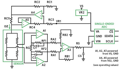
Fig 3. An example circuit for amplifying the signal from a Wheatstone bridge piezoresistive pressure sensor
How does the Output Circuitry Work?
The output circuitry of a pressure transmitter is responsible for converting the raw electrical signal generated by the pressure sensor into a format that can be easily interpreted and used by external devices, such as control systems, data acquisition systems, or displays. The specific workings of the output circuitry depend on the type of output signal the pressure transmitter is designed to provide, which can include analog voltage, analog current, or digital output. Here's how each type typically works:
Analog Voltage Output:
Analog Current Output (e.g., 4-20 mA):
Digital Output (e.g., HART, Modbus):

Fig 4. Half-Bridge-Strain-Gauge-EN-Image
How Many Output Circuitry Types Exist?
There are several types of output circuitry commonly used in various sensors and transmitters to communicate data or measurements to external devices. The choice of output circuitry depends on the specific application, requirements, and compatibility with the receiving equipment. Here are some of the most common output circuitry types:
- Analog Voltage Output: This type of output provides a continuous voltage signal that varies proportionally with the measured parameter. Common voltage ranges include 0-5V and 0-10V.
- Analog Current Output (Current Loop): In this configuration, a continuous current signal is used to represent the measured parameter. A common standard is the 4-20 mA current loop, where 4 mA typically corresponds to the minimum measurement value, and 20 mA corresponds to the maximum value.
- Digital Output: Digital output circuitry represents data in a digital format. Various communication protocols are used, includinga. HART (Highway Addressable Remote Transducer): HART is a digital communication protocol often used in process automation and control. It combines analog and digital signals on a single wire, allowing for both process variables and additional information to be transmitted.b. Modbus: Modbus is a widely used serial communication protocol for industrial devices. It supports both analog and digital data transmission and is commonly used in SCADA (Supervisory Control and Data Acquisition) systems.c. Profibus: Profibus is another industrial communication protocol used for real-time data exchange between field devices and control systems. It offers fast data transmission rates and is often used in manufacturing and process control.d. CAN (Controller Area Network): CAN is a common protocol in automotive and industrial applications. It's known for its robustness and is used for both analog and digital data transmission.e. Ethernet/IP: Ethernet/IP is an industrial Ethernet protocol used for real-time control and automation. It allows for high-speed data transfer and is suitable for various applications.
- Frequency Output: Some sensors and transmitters provide frequency-based output signals. The frequency of the signal varies in proportion to the measured parameter.
- Switch or Relay Output: In certain applications, sensors provide binary outputs, such as an open or closed switch or relay contact. These are often used for limit or alarm conditions.
- PWM (Pulse Width Modulation): PWM output represents data by varying the duty cycle (percentage of time the signal is high) of a pulse signal. It is often used in control systems.
- RS-232 and RS-485: These are serial communication standards used for transmitting data between devices. While not specific to sensors, they are used in various applications for data transmission.
- 4-20 mA with HART: Some devices combine the 4-20 mA analog current signal with HART digital communication for added functionality and diagnostics.
The choice of output circuitry depends on factors such as the type of sensor or transmitter, the communication requirements of the application, the distance over which the signal needs to be transmitted, and the compatibility with receiving equipment and control systems.
Analog Voltage Output:
- Simple to use and understand.
- Suitable for many types of measurement.
- Compatible with a wide range of analog input devices.
- Limited transmission distance without signal degradation.
- Vulnerable to noise interference.
Analog Current Output (Current Loop):
- Excellent noise immunity, suitable for harsh industrial environments.
- Can transmit data over long distances without signal loss.
- Easy to detect circuit faults (e.g., open or short circuits).
- More complex than voltage output for some users.
- Requires a current receiver at the receiving end.
Digital Output (e.g., HART, Modbus):
- Precise and error-resistant data transmission.
- Supports bidirectional communication for configuration and diagnostics.
- Suitable for complex industrial control systems.
- Requires compatible communication equipment.
- Higher setup complexity compared to analog output.
Frequency Output:
- Well-suited for applications requiring counting or timing.
- Can be easily interfaced with digital counters and controllers.
- May require additional components for data interpretation.
- Limited range compared to analog signals.
Switch or Relay Output:
- Simple and robust for basic control and safety applications.
- Instant response to threshold conditions.
- Limited to binary control (on/off).
- Less information compared to analog or digital output.
PWM (Pulse Width Modulation):
- Precise control of devices.
- Efficient for motor control and power regulation.
- Requires pulse-width modulation circuitry for interpretation.
- It is not as common as other output types in many applications.
RS-232 and RS-485:
- Description: RS-232 and RS-485 are serial communication standards used for transmitting data between devices. They can be used for both analog and digital data transmission.
- Operation: Data is transmitted serially using voltage levels in the case of RS-232 or differential signaling in the case of RS-485.
- Applications: RS-232 and RS-485 are used in various applications, including data communication between computers and peripherals, industrial automation, and equipment interfacing.
- Devices: Many devices, including sensors, PLCs, and industrial controllers, support RS-232 and RS-485 communication.
- Pros:
- Versatile and widely supported in many industries.
- Suitable for both short and long-distance data transmission.
- Cons:
- Limited transmission speed compared to modern Ethernet-based protocols.
- Configuration and wiring can be complex for more extensive networks.
Comparing table
Here's a comparison table summarizing the characteristics of different types of output circuitry commonly used in sensors and transmitters:
Table 1. Comparing output circuit types
| Output Type | Description | Operation | Common Applications | Devices | Pros | Cons |
| Analog Voltage Output | Provides continuous voltage signal | The voltage varies linearly with the parameter | Temperature sensing, pressure sensing, flow rate measurement | Temperature sensors, pressure transducers, flow meters | Simple to use, broad compatibility | Limited transmission distance, vulnerable to noise interference |
| Analog Current Output | Provides continuous current signal (e.g., 4-20 mA) | Current varies linearly with parameter | Process control, automation, industrial monitoring | Pressure transmitters, level sensors, industrial sensors | Excellent noise immunity, long-distance transmission | More complex for some users, and requires the current receiver at the receiving end |
| Digital Output (e.g., HART, Modbus) | Encodes data in digital format | Data is transmitted digitally via protocols | Industrial automation, control systems, data acquisition | Pressure transmitters, flow meters, temperature controllers | Precise and error-resistant communication supports bidirectional communication | Requires compatible communication equipment, higher setup complexity |
| Frequency Output | Generates a signal with variable frequency | Frequency varies with the parameter | Speed monitoring, flow measurement, counting applications | Tachometers, flow meters, some position sensors | Suitable for counting or timing, easy interfacing | Limited range compared to analog signals |
| Switch or Relay Output | Provides binary signal (e.g., open or closed) | State changes based on a threshold condition | Limit switches, safety interlocks, alarm systems | Limit switches, safety sensors, some industrial sensors | Simple and robust for basic control and safety | Limited to binary control (on/off), less information |
| PWM (Pulse Width Modulation) | The duty cycle of a pulse signal | The duty cycle represents the parameter being measured | Motor speed control, LED dimming, power regulation | Motor controllers, LED drivers, some control systems | Precise control of devices, efficient for motor control | Requires PWM circuitry for interpretation, less common in some applications |
| RS-232 and RS-485 | Serial communication standards | Data is transmitted serially using voltage levels or differential signaling | Data communication, industrial automation, equipment interfacing | Sensors, PLCs, industrial controllers, computers | Versatile, suitable for short and long-distance transmission | Limited transmission speed compared to modern Ethernet-based protocols, complex wiring for larger networks |
Please note that the suitability of a particular output circuitry depends on the specific requirements of your application, including factors like transmission distance, noise immunity, data precision, and compatibility with receiving equipment. The choice should align with the needs and constraints of your project.
Pressure sensor Output Type
Pressure sensors are used to measure pressure in various applications, and they can have different output types, each suited to specific requirements. Here's an explanation of common pressure sensor output types:
Analog Voltage Output:
Cons: Vulnerable to noise interference, limited transmission distance without signal amplification.
Analog Current Output (Current Loop):
Cons: Requires a current receiver at the receiving end, slightly more complex for some users compared to the voltage output.
Digital Output (e.g., I2C, SPI, UART):
Cons: Requires a compatible communication interface and protocol, and may have higher power consumption compared to analog sensors.
Frequency Output:
Cons: Limited to applications where frequency-based measurements are relevant, additional components may be needed for data interpretation.
Switch or Relay Output:
Cons: Limited to binary control (on/off), provides less information than analog or digital output.
The choice of pressure sensor output type depends on the specific requirements of the application, including factors like data transmission distance, noise tolerance, data precision, and compatibility with receiving equipment or control systems.
Comparing table
Here's a comparison table summarizing the characteristics of different pressure sensor output types:
Table 2. Comparing pressure sensor output types
| Output Type | Description | Operation | Common Applications | Pros | Cons |
| Analog Voltage Output | Provides continuous voltage signal | The voltage varies linearly with pressure | HVAC, pneumatic controls, industrial automation | Simple to interface, easy to calibrate | Vulnerable to noise, limited transmission distance without signal amplification |
| Analog Current Output (Current Loop) | Provides continuous current signal (e.g., 4-20 mA) | Current varies linearly with pressure | Process control, manufacturing, oil and gas | Robust, excellent noise immunity, long-distance transmission | Requires a current receiver at the receiving end, slightly more complex for some users compared to the voltage output |
| Digital Output (e.g., I2C, SPI, UART) | Provides digital data through communication interfaces | Pressure readings are encoded digitally and transmitted as data packets | Consumer electronics, automotive systems, medical devices | Precise and error-resistant data transmission, suitable for complex control systems | Requires compatible communication interface, potentially higher power consumption |
| Frequency Output | Generates a frequency signal that varies with pressure | Frequency changes with pressure | Flow rate measurement, tachometers, speed sensing | Suitable for counting or timing applications, easy interfacing with digital counters and controllers | Limited to applications where frequency-based measurements are relevant, additional components may be needed for data interpretation |
| Switch or Relay Output | Provides binary signals based on threshold conditions | Changes state when pressure crosses predefined thresholds | Limit switches, safety interlocks, basic on/off control | Simple and robust for basic control and safety applications, instant response to threshold conditions | Limited to binary control (on/off), provides less information than analog or digital output |
The choice of pressure sensor output type should align with the specific needs of the application, considering factors such as data transmission distance, noise tolerance, data precision, and compatibility with receiving equipment or control systems. Each type has its advantages and disadvantages, making it suitable for different scenarios and requirements.

Fig 5. Pressure sensor output
What are the Important Factors in Choosing the Right Output Circuitry?
Choosing the right output circuitry for a sensor or measurement device is crucial to ensure the effectiveness and compatibility of the system. Several important factors should be considered when selecting the appropriate output circuitry:
1.Application Requirements:
Environmental Conditions:Assess the level of electrical noise or interference in the environment where the sensor will operate. Analog current output or digital communication may be more suitable in noisy environments
5.Power Supply:
Power Availability:Ensure that the chosen output circuitry is compatible with the available power supply voltage and current.
6.Interference and Interactions:
7.Data Processing and Interpretation:
Ease of Data Interpretation: Consider the ease of data interpretation and processing. Digital outputs often provide more structured and error-resistant data.
8.Maintenance and Calibration:
9.Cost Considerations:
10.Industry Standards:
11.Future Expansion:
12.Environmental Conditions:
Temperature and Pressure: Ensure that the selected output circuitry can operate within the expected temperature and pressure ranges of the application.
13.Safety Considerations:
Conclusion
Selecting the appropriate output circuitry for a sensor or measurement device is a critical decision that directly impacts the effectiveness and compatibility of the system. In conclusion, here are the key takeaways:
1.Consider the Application Requirements: Start by understanding the nature of the measurement and the specific requirements for the parameter you are measuring. Different applications may require different output types based on accuracy, response time, and precision.
2.Evaluate Compatibility: Ensure that the chosen output circuitry is compatible with the receiving equipment, data acquisition systems, or control systems that will process the sensor data. Consider communication standards and interfaces.
3.Transmission Distance and Noise Immunity: Take into account the transmission distance of the signal and the level of electrical noise or interference in the operating environment. Analog current output is often preferred for long-distance transmission and noisy environments.
4.Consider Interference and Interactions: Assess potential electromagnetic interference and interactions with other devices or systems in the application. Proper isolation may be necessary to prevent interference.
5.Data Processing and Maintenance: Consider ease of data interpretation and processing, especially if interfacing with software. Evaluate calibration and maintenance requirements for the chosen output circuitry.
6.Cost and Compliance: Factor in the cost implications of the chosen output circuitry, including any additional components or equipment required. Ensure compliance with industry standards and regulations.
7.Scalability and Future Expansion: Assess whether the chosen output circuitry allows for future system expansion or upgrades without significant redesign.
8.Environmental Conditions and Safety: Ensure that the selected output circuitry can operate within the expected temperature, pressure, and safety standards applicable to the application. By carefully considering these factors, you can make an informed decision when selecting the right output circuitry for your sensor or measurement device. This will help ensure accurate measurements, reliable performance, and successful integration into your application.
To Recap
1.What is output circuitry in sensors and devices?Answer: Output circuitry in sensors and devices refers to the electrical circuit or interface that generates signals to represent measurements or data collected by the sensor. It determines how the sensor communicates with external systems or displays.
2.Why are different output circuitry types used in sensors?Answer: Different output circuitry types are used to meet the specific needs of various applications. The choice depends on factors like data transmission distance, noise immunity, compatibility, and the requirements of the receiving equipment.
3.What is the difference between analog 3.and digital output circuitry?Answer: Analog output provides a continuous signal that varies proportionally with the measured parameter, while digital output encodes data in a discrete digital format, often using binary values (0s and 1s).
4.When is analog voltage output preferred over analog current output?Answer: Analog voltage output is often preferred when the receiving equipment or input devices are designed to accept voltage signals. It may also be chosen for simplicity in certain applications.
5.What are the advantages of using analog current output (4-20 mA) in industrial settings?Answer: Analog current output is known for its noise immunity and suitability for long-distance transmission, making it ideal for industrial applications where data integrity over long cables is crucial.
6.In which applications is digital output, such as Modbus or HART, commonly used?Answer: Digital output is common in industrial automation, control systems, and data acquisition systems where accurate and structured data transmission is required, along with additional information like diagnostics.
7.When would you use frequency output in sensors? Answer: Frequency output is used in applications requiring counting or timing, such as tachometers, flow rate measurement, and speed sensing.
8.What are the typical applications for sensors with switch or relay outputs? Answer: Sensors with switch or relay outputs are used for limit or alarm conditions, safety interlocks, and basic on/off control in various industries.
9.What is the advantage of using PWM (Pulse Width Modulation) output in certain applications? Answer: PWM output provides precise control of devices, making it suitable for applications like motor speed control, LED dimming, and power regulation.
10.What are RS-232 and RS-485 outputs commonly used for?Answer: RS-232 and RS-485 are serial communication standards used for data transmission between devices, making them versatile and widely used in various industries, including industrial automation and equipment interfacing.
11.What factors should be considered when choosing the right output circuitry for a sensor?Answer: Factors to consider include application requirements, compatibility with receiving equipment, transmission distance, noise immunity, data processing, cost, compliance, scalability, environmental conditions, and safety standards.
12.What is the importance of considering noise immunity in output circuitry selection?Answer: Noise immunity ensures that the sensor's output signal remains accurate and reliable in the presence of electrical interference, which is crucial in noisy industrial environments.
13.How can you ensure the selected output circuitry complies with safety standards? Answer: To ensure compliance with safety standards, choose output circuitry and sensors that meet the relevant safety regulations for your specific application and industry.
14.What are the benefits of using digital communication protocols like Modbus or HART in sensors?Answer: Digital communication protocols provide precise and error-resistant data transmission, bidirectional communication for configuration and diagnostics, and compatibility with advanced control systems.
15.Can the choice of output circuitry affect the scalability of a sensor system?Answer: Yes, the choice of output circuitry can affect the scalability of a sensor system. Some output types may be more easily integrated into larger systems or allow for future expansion, while others may require significant changes for scalability.
Reference
https://www.futek.com/pressure-transducer
https://www3.panasonic.biz/ac/ae/service/tech_support/fasys/tech_guide/pressure/index.jsp
Recent Posts
-

Booster Pump Troubleshooting and Maintenance: How to Fix and Prevent Common Issues
1. Introduction Imagine turning on your faucet only to be greeted with a weak trickle of water when …22nd Apr 2025 -

Energy-Efficient Booster Pumps: Selection and Tips for Maximizing Performance
1. Introduction Imagine never having to deal with fluctuating water pressure, noisy pumps, or skyroc …19th Apr 2025 -

Booster Pumps for Sustainable Water Systems: Irrigation and Rainwater Harvesting Solutions
1. Introduction Water scarcity is no longer a distant threat—it’s a reality affecting millions …16th Apr 2025