null
Connecting the Dots: Demystifying Pressure Sensor Electrical Connections

Connecting the Dots: Demystifying Pressure Sensor Electrical Connections

Pressure sensors are fundamental components in various industrial, automotive, and consumer applications, playing a crucial role in monitoring and controlling pressure levels. Achieving accurate and reliable pressure measurements hinges on the effectiveness of electrical connections. A thorough understanding of the electrical aspects is vital for ensuring optimal sensor performance, system efficiency, and safety.

In this context, this introduction delves into the key considerations surrounding pressure sensor electrical connections. From the types of electrical connections commonly employed to the impact of cable length and the intricacies of connecting sensors in hazardous areas, we explore the essential aspects that users, engineers, and technicians need to navigate for successful pressure sensor integration.

The journey begins with an exploration of the common types of electrical connections, ranging from analog outputs to digital communication protocols and Wheatstone bridge configurations. We then delve into the practical aspects of identifying the correct wiring configuration, emphasizing the importance of referring to datasheets and manuals for precise information.

Moving forward, we address the critical issue of cable selection, emphasizing the need for specialized cables to ensure insulation and signal integrity. The discussion extends to cable considerations for analog and digital output signals, shedding light on the types of cables suitable for each scenario.

Safety takes center stage as we unravel the precautions and measures necessary when connecting pressure sensors to electrical circuits. From proper grounding techniques to the meticulous handling of connections, this section provides insights to mitigate risks and ensure a secure operating environment.

The complexities of connecting pressure sensors in hazardous areas demand a dedicated exploration. We outline the unique challenges, emphasizing explosion protection measures, equipment selection, and compliance with regulatory standards to guarantee safety in potentially volatile environments.

As the connection process unfolds, troubleshooting emerges as a critical skill. We detail the systematic approach to identifying and resolving electrical issues, ensuring a robust and fault-free sensor integration.

Ensuring proper insulation and protection becomes paramount, especially when pressure sensors operate in challenging environments. This introduction outlines the best practices, including cable routing, enclosure selection, and regular maintenance checks, to safeguard against environmental factors and physical stress.

Closing the introduction is a set of frequently asked questions, addressing common queries about pressure sensor electrical connections. From cable types to troubleshooting methods, these FAQs serve as a handy reference for those navigating the intricacies of pressure sensor integration.

In essence, this comprehensive introduction serves as a valuable resource, offering insights and guidance for individuals involved in the installation, maintenance, and optimization of pressure sensor electrical connections across diverse applications. Whether you are an engineer designing a sophisticated industrial system or a technician troubleshooting a sensor network, this introduction provides a solid foundation for success in the realm of pressure sensing.

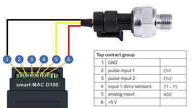
Fig 1. Connection diagram pressure sensor to smart-MAC D105

Pressure sensor electrical connections

Pressure sensors typically have electrical connections that vary depending on the type and model of the sensor. However, there are some common types of electrical connections for pressure sensors:

  • Analog Output (Voltage or Current): Many pressure sensors have analog outputs, such as voltage (e.g., 0-5V) or current (e.g., 4-20mA). These sensors usually have multiple wires for power (usually red for positive and black for ground) and output (typically a different color, like white or blue).
  • Digital Output (I2C, SPI, UART): Some modern pressure sensors offer digital outputs using protocols like I2C, SPI, or UART. These sensors usually have power supply wires (positive and ground) along with communication wires (data and clock lines for I2C, MOSI/MISO for SPI, or TX/RX for UART).
  • Bridge Configuration (Wheatstone Bridge): Certain pressure sensors use a Wheatstone bridge configuration, which requires connections to multiple terminals or pins for excitation voltage and differential voltage measurement.
  • In any case, it's essential to refer to the datasheet or the manufacturer's instructions for the specific pressure sensor model you're using. The datasheet will provide detailed information on how to correctly wire and connect the sensor to your circuit or system, including pin configurations, power requirements, and signal outputs.

    If you have a particular pressure sensor in mind or specific requirements, I could help with more precise instructions or guidance!

    How does a pressure transmitter connect electrically?

    A pressure transmitter typically connects electrically in a way that allows it to measure pressure and send the corresponding signal to a monitoring or control system. These transmitters often have standardized wiring configurations, but specifics can vary based on the manufacturer and model. However, I can provide a general idea of how a pressure transmitter might connect electrically:

  • Power Supply: Pressure transmitters usually require power to operate. Commonly, they require a DC power supply, often within the range of 12-36 volts DC. The positive and negative terminals of the power supply connect to the appropriate terminals on the transmitter. These terminals might be labeled as "+V" for positive voltage and "GND" for ground.
  • Signal Output: Pressure transmitters typically have an output signal that represents the measured pressure. This signal can be analog (such as a voltage or current) or digital (using communication protocols like HART, Profibus, Modbus, etc.).
    • Analog Output: If it's an analog output, there will be terminals for the signal output. For instance, a 4-20mA output might have terminals labeled "OUT+" and "OUT-" for the positive and negative sides of the signal, respectively. You'd connect these terminals to your monitoring or control system.
    • Digital Output: If the transmitter has a digital output, it may use specific communication protocols like HART, Modbus, etc. In this case, the transmitter will have terminals for data communication (like Tx, Rx, clock, data lines, etc.) that connect to a compatible receiver or controller.
  • Shielding: Some transmitters have a separate terminal for shielding or grounding. This helps minimize electrical interference and noise in the signal. It's usually connected to the ground or a dedicated grounding point in the system.
  • Always refer to the transmitter's datasheet or manual for accurate and specific information regarding the wiring and electrical connections. The datasheet will provide details on terminal labels, recommended power supply specifications, signal output types, and proper wiring techniques for your particular pressure transmitter model.

    Power supply connections of pressure sensor

    The power supply connections for a pressure sensor are crucial for its proper operation and accurate readings. These connections ensure the sensor receives the necessary electrical power to function and transmit pressure-related data reliably.

    Typically, pressure sensors require a direct current (DC) power supply within a specified voltage range, commonly between 5 to 36 volts DC, depending on the sensor's design and specifications. The positive and negative terminals of the power supply connect to designated terminals on the pressure sensor. These terminals are usually labeled explicitly, such as "+V" for positive voltage and "GND" for ground or negative.

    Ensuring the correct polarity is essential. Reversing the polarity could potentially damage the sensor. Therefore, it's vital to double-check the wiring against the sensor's datasheet or manual before applying power.

    Stable and clean power is essential for accurate pressure measurements. Noisy or fluctuating power sources might introduce interference that affects the sensor's output accuracy. Some sensors may have specific requirements for power conditioning or recommend additional measures, such as using a dedicated power regulator or ensuring proper grounding to minimize electrical noise.

    Additionally, when connecting the power supply to the pressure sensor, it's crucial to consider the overall system's power requirements and potential power draw from multiple sensors or components sharing the same power source. Ensuring an adequate power supply capacity can prevent voltage drops or fluctuations that might affect sensor performance.

    Lastly, proper insulation and protection of the power supply connections are essential, especially in industrial or harsh environments where exposure to moisture, dust, or vibrations can compromise the electrical connections. Adequate insulation and protective measures, such as using suitable enclosures or sealing techniques, help maintain the integrity of the power connections, ensuring the sensor operates reliably over its intended lifespan.

    Pressure sensor signal output connections

    The signal output connections of a pressure sensor are pivotal as they transmit the measured pressure data to external systems or devices for analysis, monitoring, or control purposes. These connections are where the sensor communicates its readings in a format compatible with the receiving equipment.

  • Voltage or Current Signals: Some pressure sensors generate analog output signals, commonly in the form of voltage (e.g., 0-5V) or current (e.g., 4-20mA). These sensors usually have dedicated terminals for signal output. For example, terminals might be labeled "OUT+" and "OUT-" for the positive and negative sides of the signal, respectively.
  • Wiring: These output terminals connect to the input terminals of the receiving device or system, such as data loggers, controllers, or PLCs (Programmable Logic Controllers). Wiring the output signal correctly is critical to ensure accurate transmission of pressure data without interference.
  • Digital Output:
    • Communication Protocols: Some modern pressure sensors offer digital output using communication protocols like I2C, SPI, UART, HART, Modbus, Profibus, etc.
    • Multiple Wires: These sensors often have multiple wires for different purposes, such as power supply, data, clock, and ground. Each wire connects to the corresponding terminal on the receiving device compatible with the sensor's communication protocol.
  • Signal Integrity:
    • Interference Minimization: Proper shielding and grounding techniques help minimize electromagnetic interference that could affect the integrity of the signal. Some sensors have a separate shielding terminal, which connects to the ground to reduce noise in the signal.
  • Connector Types:
    • Connectors or Terminal Blocks: Depending on the sensor's design, these connections may use various connector types or terminal blocks for ease of installation and maintenance.
  • It's crucial to consult the sensor's datasheet or manual to correctly identify and connect the signal output terminals. The datasheet provides detailed information about the pin configuration, signal types, wiring diagrams, and recommended connection methods specific to the sensor model. Ensuring proper signal output connections is essential for accurate and reliable transmission of pressure data to downstream systems for effective monitoring and control.

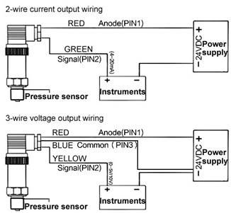
    Fig 2. Two wire and three wire pressure sensor wiring diagram

    Which type of cable use for analog output signal in electrical connection for pressure sensor?

    For transmitting analog output signals from pressure sensors, the choice of cable often depends on factors such as signal integrity, distance, and environmental conditions. Here are some commonly used cables for transmitting analog signals from pressure sensors:

  • Shielded Twisted Pair Cable (STP): This cable consists of pairs of insulated wires twisted together, with an overall shielding layer. It's effective in reducing electromagnetic interference (EMI) and radio frequency interference (RFI), ensuring better signal integrity. STP cables are suitable for moderate distances and environments with potential electromagnetic disturbances.
  • Coaxial Cable: Coaxial cables feature a central conductor surrounded by insulation, a metallic shield, and an outer insulating layer. While they're more commonly associated with higher-frequency applications, certain pressure sensors with specific analog outputs might benefit from coaxial cables, particularly when the signal quality needs extra protection from external interference.
  • Multi-Conductor Cable with Shielding: These cables contain multiple insulated conductors within a single cable, often with an overall shielding layer. They offer flexibility and can accommodate various signals within one cable, providing protection against interference.
  • Instrumentation Cable: Specifically designed for transmitting low-voltage signals with minimal interference, instrumentation cables often feature twisted pairs or triads, ensuring signal accuracy and stability. They're suitable for analog signals in industrial settings.
  • When selecting a cable for the analog output signal from a pressure sensor, consider the distance the signal needs to travel, potential sources of interference in the environment, and the requirements specified in the sensor's datasheet. Ensuring proper shielding, impedance matching, and cable quality is crucial for maintaining signal integrity and accuracy. Always refer to the sensor's documentation or manufacturer recommendations for the most suitable cable type for your specific application.

    Which type of cable use for digital output signal in electrical connection for pressure sensor?

    The type of cable used for transmitting digital output signals from a pressure sensor depends on the communication protocol the sensor employs and the specific requirements of the application. Here are some common cable types for transmitting digital signals:

  • Twisted Pair Cable (for Low-Speed Digital Signals): For low-speed digital signals, twisted pair cables can be used. These cables consist of pairs of insulated wires twisted together, providing basic noise immunity for signals transmitted over short distances. They are often suitable for protocols like UART (Universal Asynchronous Receiver-Transmitter) or some implementations of I2C.
  • Twisted Pair or Shielded Twisted Pair Cable (for Moderate-Speed Signals): Some digital communication protocols like Modbus, HART, or some configurations of I2C and SPI might benefit from twisted pair cables, especially shielded twisted pair cables. They offer better noise immunity and are suitable for moderate-speed digital signals transmitted over longer distances.
  • High-Speed Data Cable (for High-Speed Digital Signals): For high-speed digital protocols like SPI (Serial Peripheral Interface) or higher-frequency versions of I2C, cables designed for high-speed data transmission may be necessary. These cables have characteristics optimized for reducing signal degradation at higher frequencies and might include shielding and specific impedance control.
  • Dedicated Data Communication Cables: Some industrial-grade communication protocols like Profibus or Ethernet-based protocols might require specialized cables designed explicitly for these communication standards. These cables often have specific requirements regarding impedance, shielding, and data transmission characteristics.
  • When choosing a cable for the digital output signal of a pressure sensor, refer to the sensor's datasheet or the manufacturer's recommendations to identify the supported communication protocol and any specific cable requirements. Ensuring proper cable selection, considering factors such as shielding, impedance matching, and noise immunity, is crucial for reliable transmission of digital signals and overall system performance.

    How can choose the proper electrical cable and connectors for pressure sensor?

    Choosing the proper electrical cable and connectors for a pressure sensor involves considering several key factors to ensure reliable and accurate signal transmission. Here's a guide to help in the selection process:

    1. Understand Sensor Specifications:


    • Check the Datasheet:Review the sensor's datasheet for recommended cable types, connector specifications, and any specific requirements provided by the manufacturer.
    • Signal Type: Determine whether the sensor outputs analog or digital signals.
    • Voltage/Current Ratings: Note the voltage and current requirements for the sensor's power supply and signal output.

    2. Consider Environmental Conditions:

    • Temperature and Moisture: Select cables and connectors rated for the operating temperature range and environmental conditions where the sensor will be installed.
    • Chemical Exposure: If the sensor will be exposed to chemicals, choose cables and connectors that resist corrosion and degradation.

    3. Cable Type Selection:

    • Analog Signals: For analog signals, consider shielded cables like shielded twisted pair (STP) or coaxial cables for better noise immunity.
    • Digital Signals: Choose cables appropriate for the digital communication protocol used by the sensor (e.g., twisted pair, high-speed data cables, or specialized cables for specific protocols).

    4. Connector Selection:

    • Compatibility: Ensure the connectors match the cable type and are compatible with the sensor's connector specifications.
    • Sealing and Durability: Select connectors with appropriate sealing against moisture and dust if the sensor will be installed in harsh environments.
    • Correct Pin Configuration: Verify that the connectors match the pin configuration of the sensor's output (analog or digital) and power supply.

    5. Cable Length and Shielding:

    • Length: Keep cable lengths within the specified limits to maintain signal integrity, especially for analog signals prone to interference over longer distances.
    • Shielding: Choose cables with adequate shielding to minimize electromagnetic interference, especially in industrial settings with potential sources of noise.

    6. Compliance and Standards:

    Compliance: Ensure that the selected cables and connectors comply with relevant industry standards for electrical safety and performance.

    7. Consult Manufacturer Guidelines:

    Manufacturer Recommendations: If available, follow the manufacturer's guidelines and recommendations for cable and connector selection to ensure optimal performance and reliability.

    8. Test and Validate:

    Testing: Before deployment, conduct tests to ensure the selected cables and connectors perform as expected and meet the sensor's requirements.

    By considering these factors and consulting the sensor's documentation or manufacturer guidelines, you can choose electrical cables and connectors that suit the sensor's specifications, environmental conditions, and intended application, ensuring reliable signal transmission and accurate readings.

    Installation of appropriate electrical cables and connectors

    Installing electrical cables and connectors for a pressure sensor requires attention to detail and following best practices to ensure reliable operation and accurate signal transmission. Here's a step-by-step guide for their installation:

    1. Gather Required Components:

    • Cables: Select the appropriate cables based on the sensor's specifications and environmental conditions.
    • Connectors: Choose connectors that match the cable type and are compatible with the sensor's connector specifications.

    2. Prepare the Area:

    • Safety: Ensure the area is safe for installation, following proper safety protocols and wearing necessary protective gear.
    • Clean Environment: Work in a clean environment, free from dust, moisture, or potential contaminants.

    3. Cut and Strip Cables:

    • Measure and Cut: Measure and cut the cables to the required lengths, ensuring they aren't excessively long or too short.
    • Strip Insulation: Use wire strippers to carefully remove the outer insulation of the cables, exposing the inner wires for connection.

    4. Connect Cables to Connectors:

    • Follow Guidelines: Refer to the sensor's datasheet or manufacturer guidelines for the correct pin configuration.
    • Soldering or Crimping: Depending on the connector type, solder or crimp the wires securely to the connector pins, ensuring proper connections without any loose wires.

    5. Ensure Proper Insulation:

    • Insulate Connections: Use heat shrink tubing, electrical tape, or appropriate insulation material to cover and secure the connections, preventing short circuits or exposure to external elements.

    6. Test Connections:

    • Check Continuity: Use a multimeter to check for continuity and ensure there are no short circuits or loose connections in the cables and connectors.
    • Functional Test: Test the sensor's output to verify that the electrical connections are properly transmitting the signal.

    7. Secure Cables and Connectors:

    Secure Mounting: Securely fasten the cables and connectors in place using suitable mounting brackets, cable ties, or clamps to prevent movement or strain on the connections.

    8. Seal and Protect:

    • Weatherproofing: If the installation is outdoors or in a harsh environment, apply appropriate sealants or weatherproofing materials around the connectors to prevent moisture ingress.
    • Use Protective Covers: Employ protective covers for connectors or use enclosures to shield connections from environmental hazards.

    9. Document and Label:

    • Documentation: Maintain records of the installation, including cable types, connector specifications, and connection diagrams for future reference.
    • Labeling: Label cables and connectors clearly for easy identification during maintenance or troubleshooting.

    10. Follow Regulations and Standards:

    Compliance: Ensure compliance with electrical codes, standards, and regulations applicable to your installation.

    By following these steps and paying attention to detail during the installation process, you can establish reliable electrical connections for your pressure sensor, promoting accurate signal transmission and ensuring the longevity of the sensor system. If unsure, consulting an electrician or following specific industry guidelines can further enhance the installation process.

    Wiring considerations for analog and digital output signals

    Wiring considerations for analog and digital output signals from pressure sensors involve different factors due to the nature of these signals. Here are some considerations for each:

    Analog Output Signals:

  • Signal Integrity:
    • Noise Reduction: Use shielded cables (like shielded twisted pair or coaxial) to minimize electromagnetic interference (EMI) and maintain signal integrity, especially for longer cable runs.
    • Proper Grounding: Ensure proper grounding techniques to reduce noise and interference in the analog signal.
  • Cable Length and Resistance:
    • Signal Degradation: Longer cable lengths can lead to signal degradation due to increased resistance and capacitance. Keep cable lengths within recommended limits.
    • Higher Gauge Wires: For longer distances, consider using wires with a larger gauge to minimize resistance.
  • Connector Quality:
    • High-Quality Connectors: Use high-quality connectors to maintain a secure and reliable connection, preventing signal loss or interference.
  • Digital Output Signals:

  • Impedance Matching:
    • Match Impedance: Ensure proper impedance matching between the sensor, cable, and receiving device to prevent signal reflection and loss.
    • Twisted Pair for Noise Reduction: Twisted pair cables help reduce electromagnetic interference for digital signals.
  • Cable Type and Length:
    • Type of Digital Cable: Select cables appropriate for the digital protocol used (e.g., twisted pair, high-speed data cables).
    • Length Consideration: Maintain cable lengths within the specified limits to prevent signal degradation.
  • Connector Quality and Compatibility:
    • Correct Connectors: Use connectors compatible with the digital signal type and ensure they meet the required specifications.
    • Proper Termination: Ensure proper termination of digital signal cables to prevent signal reflections.
  • Common Considerations for Both Analog and Digital:

  • Cable Routing:
    • Separation from Power Cables: Keep signal cables away from high-voltage power cables to prevent interference.
    • Avoiding Sharp Bends: Minimize sharp bends and kinks in the cables to avoid signal distortion or damage.
  • Environmental Factors:
    • Protection from Environmental Hazards: Use appropriate cable insulation and protection against moisture, chemicals, temperature extremes, and physical damage.
    • Use of Cable Conduits or Enclosures: Protect cables in harsh environments with conduits or enclosures.
  • Testing and Validation:
    • Functionality Testing: Before final installation, test the cables and connections to ensure proper functionality and signal transmission.
    • Periodic Maintenance: Regularly inspect and maintain the cables and connections to avoid signal disruptions due to wear or damage.
  • By considering these factors and adhering to manufacturer guidelines and specifications, you can effectively wire analog and digital output signals from pressure sensors, ensuring reliable and accurate data transmission in various applications.

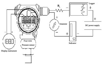
    Fig 3. Four wire pressure sensor wiring diagram

    Grounding requirements for pressure transmitters

    Grounding for pressure transmitters is crucial for system safety, signal integrity, and interference reduction. Here are grounding requirements to consider:

    Safety Grounding:

  • Equipment Grounding: Ensure the pressure transmitter and associated equipment are connected to an appropriate grounding system following electrical safety standards (e.g., NEC, IEC).
  • Local Regulations: Adhere to local electrical codes and regulations regarding equipment grounding practices.
  • Signal Integrity and Noise Reduction:

  • Signal Grounding: Properly ground the signal cables to minimize electromagnetic interference (EMI) and maintain signal integrity.
  • Shielding Techniques: Use shielded cables and ensure the shielding is properly connected to ground to reduce noise pickup.
  • Separation from Power Cables: Keep signal cables separate from high-power cables to minimize induced noise.
  • Grounding Best Practices:

  • Single Point Grounding: Implement a single-point grounding system to prevent ground loops and ensure a common reference point for the equipment.
  • Low-Impedance Grounding: Maintain low impedance in the grounding system to effectively dissipate electrical faults and minimize voltage differences.
  • Clean and Secure Connections: Ensure clean and secure connections between grounding points, cables, and the grounding system to prevent signal degradation or safety hazards.
  • Grounding Conductors: Use adequate gauge conductors for grounding to minimize resistance and ensure efficient dissipation of electrical faults.
  • Periodic Inspection: Regularly inspect the grounding system to verify its effectiveness and identify any potential issues or corrosion.
  • Adhering to proper grounding practices is essential for the safe and reliable operation of pressure transmitters. Following industry standards, manufacturer recommendations, and consulting with qualified electricians or professionals can help ensure the correct implementation of grounding requirements for pressure transmitters in your specific application.

    Pressure sensor Grounding techniques

    Grounding pressure sensors properly is critical for signal accuracy, minimizing noise interference, and ensuring electrical safety. Here are some grounding techniques specific to pressure sensors:

    Signal Grounding

  • Use Shielded Cables: Employ shielded cables to reduce electromagnetic interference (EMI) affecting the sensor's output signal.
  • Connect Shielding: Ensure the shielding of the cable is properly connected to the designated ground terminal on the sensor or the system to which it's connected.
  • Separation from Power Cables: Keep sensor signal cables separated from high-voltage power cables to prevent induced noise.
  • Electrical Safety Grounding

  • Connect Chassis Ground: If the pressure sensor has a metal enclosure or chassis, connect it to the system's ground or the designated earth ground.
  • Follow Safety Standards: Adhere to electrical safety standards and local regulations when establishing the ground connection for the sensor and associated equipment.
  • Grounding Practices

  • Single-Point Grounding: Implement a single-point ground system to prevent ground loops and ensure a common reference point for the sensor and connected devices.
  • Low-Impedance Grounding: Maintain low impedance in the grounding system to effectively dissipate electrical faults and reduce voltage differentials.
  • Secure Connections: Ensure proper and secure connections between grounding points, cables, and the grounding system to prevent signal degradation or safety hazards.
  • Grounding Conductors: Use appropriate gauge conductors for grounding to minimize resistance and efficiently dissipate electrical faults.
  • Regular Inspection: Periodically inspect the grounding system to ensure its effectiveness, identify corrosion or loose connections, and maintain optimal performance.
  • Manufacturer Recommendations

    Always refer to the sensor's datasheet or manufacturer's guidelines for specific grounding instructions or recommendations. Manufacturers often provide detailed information on the sensor's grounding requirements to ensure proper installation and operation.

    Professional Assistance

    For complex grounding setups or if uncertain about the grounding requirements for your specific application, seek guidance from qualified electricians, engineers, or professionals with expertise in electrical systems and sensor installations.

    By implementing these grounding techniques and following manufacturer guidelines, you can establish effective grounding for pressure sensors, ensuring accurate signal transmission and electrical safety within your system.

    Important factors to choose the appropriate grounding techniqes

    Choosing the appropriate grounding techniques involves considering various factors to ensure effective signal transmission, electrical safety, and interference reduction. Here are important factors to consider:

    1.Signal Integrity

  • Noise Reduction:Select grounding methods that minimize electromagnetic interference (EMI) to maintain signal accuracy, especially for sensitive sensors like pressure sensors.
  • Shielding: Employ shielded cables and ensure proper connection of shielding to ground to reduce noise in signal transmission.
  • 2. Electrical Safety
  • Safety Standards: Adhere to electrical safety standards and regulations relevant to your industry or location to ensure safe grounding practices.
  • Equipment Grounding: Properly ground equipment, including pressure sensors, to prevent electrical hazards and ensure a safe working environment.
  • 3. Grounding System Design
  • Grounding Type: Choose between single-point grounding or multipoint grounding based on system complexity and to prevent ground loops.
  • Low-Impedance Path: Establish low-impedance grounding to effectively dissipate fault currents and prevent voltage differences.
  • 4. Environmental Considerations
  • Harsh Environments: Consider grounding methods that protect against corrosion, moisture, or other environmental factors that could affect the effectiveness of the grounding system.
  • Temperature Variations: Ensure that grounding materials and connections can withstand temperature variations if the installation site experiences extreme temperatures.
  • 5. System Design and Layout
  • Cable Routing: Plan cable routing to keep signal cables separate from high-power cables to prevent induced noise and interference.
  • Connector Quality: Use high-quality connectors and ensure proper connection of grounding conductors to maintain reliable connections.
  • 6. Manufacturer Guidelines
  • Reference Datasheets: Refer to the sensor manufacturer's datasheets or guidelines for specific grounding recommendations tailored to the sensor model.
  • Technical Support: Consult with the manufacturer's technical support or experts for guidance on the most suitable grounding methods for their sensors.
  • 7. Future Maintenance and Inspections
  • Accessibility: Choose grounding techniques that allow for easy access during maintenance and inspections to ensure continuity and effectiveness.
  • Periodic Checks: Plan for periodic checks and maintenance of the grounding system to identify any degradation or issues that might affect performance.
  • Considering these factors when selecting grounding techniques ensures that the chosen methods effectively maintain signal integrity, promote electrical safety, and minimize interference, contributing to a reliable and robust grounding system for pressure sensors and associated equipment.

    What are the safety tips should observe about electrical connections?

    Absolutely, electrical connections demand careful handling to ensure safety. Here are some crucial safety tips:

    1. Power Off Before Working:

  • Turn Off Power: Always switch off the power supply to the circuit or equipment before making any electrical connections or modifications.
  • Lockout/Tagout Procedures: Use lockout/tagout procedures, especially in industrial settings, to prevent accidental power restoration while working on electrical connections.
  • 2. Personal Safety:
  • Protective Gear: Wear appropriate personal protective equipment (PPE), including insulated gloves, safety goggles, and non-conductive footwear.
  • Dry Environment: Work in a dry environment and avoid conducting electrical work in damp or wet conditions.
  • 3. Proper Training and Knowledge:
  • Qualified Personnel: Ensure that individuals handling electrical connections are adequately trained and qualified for the task.
  • Understanding Systems: Understand the electrical system, the equipment being connected, and the risks associated with electrical work.
  • 4. Use Correct Tools and Equipment:
  • Insulated Tools: Use insulated tools designed for electrical work to prevent electrical shocks or short circuits.
  • Voltage Testers: Always verify that circuits are de-energized using a voltage tester before handling connections.
  • 5. Proper Wiring Practices:
  • Wire Size and Capacity: Use appropriate wire sizes and connectors that match the current and voltage requirements specified for the application.
  • Tight Connections: Ensure all connections are tight and secure to avoid overheating, arcing, or accidental disconnection.
  • 6. Avoid Overloading Circuits:
  • Avoid Overloading: Do not exceed the maximum current capacity of the circuit by connecting too many devices or appliances.
  • Distribute Loads: Distribute loads evenly across circuits and avoid daisy-chaining power strips or extension cords excessively.
  • 7. Testing and Inspections:
  • Functional Testing: After making connections, conduct functional tests to ensure proper operation and safety.
  • Regular Inspections: Periodically inspect connections for signs of wear, damage, or overheating, and promptly address any issues.
  • 8. Emergency Preparedness:
  • Emergency Plan: Have an emergency plan in place in case of electrical accidents, including knowledge of how to administer first aid for electrical shock.
  • Access to Emergency Equipment: Ensure easy access to fire extinguishers and emergency shut-offs in case of electrical fires or emergencies.
  • By adhering to these safety tips, you significantly reduce the risk of electrical hazards and ensure a safer working environment when handling electrical connections. Always prioritize safety and take necessary precautions to prevent accidents.

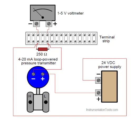
    Fig 4. Electrical connection of pressure sensor

    What are the common types of electrical connections for pressure sensors?

    Pressure sensors typically feature various types of electrical connections based on the sensor's design, application, and the desired method of signal transmission. Here are some common types of electrical connections for pressure sensors:

    1. Analog Output:

  • Voltage Output: Sensors may provide a linear voltage output (e.g., 0-5V) corresponding to the measured pressure. Electrical connections involve power supply terminals (positive and ground) and output terminals for the analog voltage signal.
  • Current Output: Some sensors offer a current output (e.g., 4-20mA) proportional to the pressure. Connections include power supply (positive and ground) and output terminals for the analog current signal.
  • 2. Digital Output:
  • Digital Communication Protocols: Modern pressure sensors may have digital outputs using communication protocols like I2C, SPI, UART, Modbus, HART, etc. These sensors utilize specific wiring configurations for data, clock, power, and ground connections.
  • 3. Wheatstone Bridge Configuration:
  • Bridge Configuration: Certain pressure sensors utilize a Wheatstone bridge configuration. These sensors require multiple electrical connections for excitation voltage and differential voltage measurement.
  • 4. Terminal Blocks or Connectors:
  • Terminal Blocks: Some sensors use terminal blocks for easy connection of wires. They may have dedicated terminals for power supply, signal output, and ground.
  • Connectors: Pressure sensors might feature connectors (e.g., M12, M8, DIN, etc.) for easier installation and maintenance. They can include pins for power, signal, and ground connections.
  • 5. Three-Wire or Four-Wire Configurations:
  • Three-Wire Setup: In some sensors, three wires are used for power supply (positive and ground) and signal output.
  • Four-Wire Setup: Four wires might be used, separating power supply (positive and ground) from signal output to minimize interference.
  • The specific type of electrical connection depends on the sensor's design, intended application, signal output (analog or digital), and manufacturer specifications. It's essential to refer to the sensor's datasheet or manual for precise information regarding the electrical connections for a particular pressure sensor model.

    How can identify the correct wiring configuration for pressure sensor?

    Identifying the correct wiring configuration for a pressure sensor involves several steps:

    1. Review the Datasheet or Manual:

  • Manufacturer Documentation: Check the sensor's datasheet or manual provided by the manufacturer.
  • Pinout Diagram: Look for a pinout diagram that illustrates the sensor's electrical connections and pin configurations.
  • 2. Understand Sensor Specifications:
  • Signal Type: Determine if the sensor outputs an analog signal (voltage or current) or a digital signal.
  • Power Requirements: Note the power supply requirements for the sensor (voltage and current).
  • 3. Visual Inspection:

    Terminals or Pins: Physically inspect the sensor for labeled terminals or pins. Common labels might include "+V" for positive voltage, "GND" for ground, "OUT" for signal output, etc.

    4. Wiring Color Codes (if applicable):

    Standardized Codes: Some sensors use standardized color codes for wiring. For instance, red for positive voltage, black for ground, white for signal, etc.

    5. Consult Manufacturer Support:

    Technical Support: Contact the manufacturer's technical support team for assistance in identifying the correct wiring configuration if there's uncertainty.

    6. Use Multimeter or Continuity Tester:

    Testing Continuity: Use a multimeter or continuity tester to check for connectivity between different terminals or wires to verify their functions.

    7. Reference Wiring Diagrams:

    Available Diagrams: Look for any wiring diagrams or installation guides provided by the manufacturer that detail the correct wiring configuration.

    8. Previous Experience or Expertise:

    Experience: If you have previous experience with similar sensors or systems, you might identify similarities in wiring configurations.

    9. Avoid Guesswork:

    Caution: Avoid making assumptions about the wiring configuration. Incorrect connections can damage the sensor or affect its performance.

    By following these steps and referring to the sensor's documentation or seeking assistance from the manufacturer's support, you can identify the correct wiring configuration for a pressure sensor. Ensuring accurate connections is crucial for the sensor's proper operation and accurate signal transmission.

    What are the standards of pressure sensor electrical connections?

    The standards for pressure sensor electrical connections can vary based on industry, application, and region. While there might not be specific universal standards solely for pressure sensor electrical connections, various overarching standards and guidelines apply to electrical connections in general, including those for pressure sensors. Here are some relevant standards and guidelines:

    1. National and International Electrical Standards:

  • NEC (National Electrical Code): The NEC sets guidelines for safe electrical installations in the United States.
  • IEC (International Electrotechnical Commission): IEC standards provide international guidelines for electrical systems and equipment.
  • 2. Industry-Specific Standards:
  • ISA (International Society of Automation): ISA standards cover instrumentation, measurement, and control systems, including guidelines for sensors.
  • ISO (International Organization for Standardization): ISO may have standards related to electrical connections in specific industries or applications.
  • 3. Safety and Compliance Standards:
  • CE Marking (ConformitĂ© EuropĂ©enne): Compliance with CE directives ensures conformity with European safety standards for electrical equipment.
  • UL (Underwriters Laboratories) Standards: UL standards address safety and performance for various electrical components and systems.
  • 4. Manufacturer Guidelines and Specifications:
  • Datasheets and Manuals: Manufacturers provide guidelines and specifications specific to their pressure sensors, detailing recommended electrical connections.
  • Technical Support: Manufacturer technical support can offer guidance on proper electrical connections based on their product specifications.
  • 5. Industrial Codes and Regulations:

    Industrial Electrical Codes: Some industries have specific electrical codes or regulations that govern equipment installations and electrical connections.

    Important Considerations:

  • Safety: Adhering to safety standards is paramount when making electrical connections to pressure sensors to prevent hazards and ensure proper operation.
  • Manufacturer Recommendations: Manufacturers often provide specific instructions and guidelines for electrical connections in their product documentation.
  • While specific standards dedicated solely to pressure sensor electrical connections might not exist, adherence to general electrical standards, industry best practices, and manufacturer guidelines ensures safe and reliable electrical connections for pressure sensors in various applications. Always consult relevant standards and manufacturer specifications when installing or connecting pressure sensors electrically.

    What precautions should take when connecting a pressure sensor to an electrical circuit?

    When connecting a pressure sensor to an electrical circuit, taking specific precautions ensures safety, accuracy, and the integrity of the sensor's operation. Here's a detailed guide:

    Before Starting:

  • Power Off: Ensure the power to the circuit is turned off before making any connections to prevent electrical hazards.
  • Review Documentation: Refer to the sensor's datasheet or manual for specific instructions on electrical connections.
  • General Precautions:
  • Personal Safety: Wear appropriate personal protective equipment (PPE), including insulated gloves and safety goggles, to prevent electrical shocks.
  • Dry Environment: Work in a dry environment and avoid handling electrical components with wet hands or in damp conditions.
  • Specific Precautions for Connection:
  • Proper Wiring Tools: Use insulated tools designed for electrical work to avoid accidental short circuits or electrical shocks.
  • Correct Polarity: Double-check the polarity of the connections, ensuring that positive and negative terminals match appropriately.
  • Terminal Compatibility: Ensure the compatibility of connectors and terminals to prevent incorrect connections or damage to the sensor.
  • Tighten Connections: Securely tighten all electrical connections to avoid loose contacts that could lead to signal disruptions or electrical hazards.
  • Grounding and Shielding:
  • Grounding: Follow proper grounding techniques as per the sensor's specifications to minimize electrical noise and ensure safety.
  • Shielded Cables: Use shielded cables as recommended by the sensor's guidelines to reduce electromagnetic interference (EMI).
  • Testing and Verification:
  • Voltage Testing: Use a multimeter or voltage tester to verify that the voltage levels are within the specified range before connecting to the sensor.
  • Continuity Check: Test for continuity to ensure that wires and connections are intact and properly connected.
  • Post-Connection Checks:
  • Functionality Test: After making connections, conduct a functionality test to ensure that the sensor is operating correctly.
  • Inspect Connections: Visually inspect all connections for any signs of damage, loose wires, or exposed terminals.
  • Documentation and Records:
  • Documentation: Maintain records of the wiring connections, noting the configuration used for future reference or troubleshooting.
  • Follow Standards: Adhere to relevant electrical codes, industry standards, and manufacturer recommendations throughout the connection process.
  • By following these precautions diligently, you ensure the safety of personnel, prevent damage to the sensor or electrical circuit, and promote accurate and reliable operation of the pressure sensor within the electrical system. Always refer to the sensor's documentation and exercise caution during the connection process.

    What is the significance of shielded cables in pressure sensor connections? in paragraphes

    Shielded cables play a crucial role in pressure sensor connections due to their ability to mitigate electromagnetic interference (EMI) and ensure signal integrity. In pressure sensor applications, where accurate and reliable data transmission is paramount, shielded cables offer several significant advantages.

    Firstly, these cables feature an additional layer of shielding, typically made of conductive material, surrounding the insulated wires carrying the signal. This shielding acts as a barrier, effectively blocking external electromagnetic fields from interfering with the signal transmitted by the pressure sensor. By doing so, shielded cables minimize the risk of signal distortion or corruption caused by EMI generated from nearby electrical equipment, power lines, or other sources of electromagnetic noise prevalent in industrial environments.

    Secondly, pressure sensors often deal with low-level analog signals susceptible to interference. Shielded cables provide a protective shield that helps maintain the integrity of these sensitive signals over longer distances. By reducing the impact of external interference, these cables ensure that the pressure sensor accurately captures and transmits the pressure data without distortion or inaccuracies caused by electrical noise.

    Moreover, shielded cables contribute to system reliability by improving the overall performance of the pressure sensor. They help maintain a stable and consistent signal, enhancing the sensor's precision and reducing the chances of erroneous readings or signal disruptions. This reliability is particularly critical in applications where precise pressure measurements are vital for safety, control systems, or sensitive industrial processes.

    In essence, the use of shielded cables in pressure sensor connections is indispensable for ensuring reliable, accurate, and noise-free transmission of signals. Their ability to mitigate electromagnetic interference significantly contributes to the sensor's performance, enabling it to deliver dependable pressure readings essential for various industrial and monitoring applications.

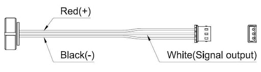
    Fig 5. Electrical connectors

    Can pressure sensors be connected in series or parallel in a circuit?

    Pressure sensors can be connected in series or parallel in a circuit, depending on the specific application requirements and the nature of the sensors being used. However, the approach to connecting pressure sensors in series or parallel can differ based on the sensor type, the intended measurement setup, and the desired outcome.

    Series Connection:

    In a series connection, multiple pressure sensors are linked sequentially, one after another, along a single path within a circuit. This arrangement allows for cumulative measurement across the sensors. Each sensor contributes to the total output or measurement, and the combined effect of all sensors' readings is measured as a single output. Series connections are often used when there's a need to measure pressure levels across multiple points in a system and obtain a total or cumulative pressure reading.

    Parallel Connection:

    In a parallel connection, multiple pressure sensors are connected separately to a circuit, running independent paths but sharing the same input source or measurement conditions. Each sensor operates autonomously and provides its individual output. Parallel connections are useful when simultaneous readings from multiple sensors are required, allowing for comparisons or monitoring of different pressure points without affecting the other sensors' measurements.

    Considerations:

  • Sensor Compatibility: Ensure that the sensors are compatible with the intended connection type. Some sensors may be designed for specific configurations and may not function optimally in series or parallel setups.
  • Signal Integrity: When connecting sensors, especially in parallel, consider potential signal interference or loading effects that might impact individual sensor readings.
  • Calibration and Accuracy: Calibration requirements may vary when sensors are connected in series or parallel. Adjustments may be needed to ensure accuracy across multiple sensors.
  • Electrical Considerations: Take into account the electrical characteristics and requirements of the sensors when planning series or parallel connections, such as power supply, signal conditioning, and compatibility with the measuring equipment.
  • Application-Specific Use:

    The choice between series or parallel connections depends on the specific application's needs, whether it's for cumulative pressure measurement, simultaneous monitoring at different points, redundancy in critical systems, or other specific requirements dictated by the operational setup.

    While pressure sensors can be connected in series or parallel, careful consideration of the sensors' characteristics, the intended measurements, and the impact on signal integrity is crucial to ensure accurate and reliable readings within the system. Consulting sensor specifications and understanding the system's requirements are essential before implementing series or parallel connections of pressure sensors.

    What's the impact of cable length on the performance of a pressure sensor?

    The impact of cable length on the performance of a pressure sensor can be significant, particularly concerning signal integrity and accuracy. Several factors come into play when considering the cable length's effect on a pressure sensor's performance:

    Signal Attenuation:

  • Resistance and Capacitance: Longer cables introduce increased resistance and capacitance, leading to signal attenuation. This attenuation can weaken the sensor's output signal, affecting accuracy.
  • Voltage Drop: Longer cables can result in voltage drops along the transmission line, affecting the voltage signal's strength, especially in analog output sensors.
  • Signal Distortion:
  • Interference and Noise: Longer cables are more susceptible to picking up electromagnetic interference (EMI) or radio frequency interference (RFI), potentially distorting the sensor's output signal.
  • Signal Delay: Longer cables may introduce signal delays, particularly in digital transmission, impacting real-time data acquisition or response in time-critical applications.
  • Calibration and Accuracy:
  • Calibration Requirements: Longer cables may necessitate adjustments in sensor calibration to compensate for signal degradation, ensuring accuracy across the extended length.
  • Measurement Error: Signal loss or distortion due to cable length can lead to measurement errors, affecting the precision and reliability of pressure readings.
  • Mitigation Strategies:
  • Use of Shielded Cables: Shielded cables help reduce EMI and RFI, maintaining signal integrity over longer distances.
  • Proper Cable Selection: Choosing cables with lower resistance and higher quality insulation suitable for the application can minimize signal degradation.
  • Signal Conditioning: Employing signal conditioning devices or amplifiers near the sensor or at the receiving end can mitigate signal loss due to longer cable runs.
  • Application Considerations:
  • System Design: Consider the application's specific requirements regarding cable length and its impact on signal transmission, especially in critical or high-precision setups.
  • Limitation of Cable Length: Adhere to the manufacturer's recommended cable length limits specified for the sensor to ensure optimal performance.
  • How can troubleshoot electrical issues with pressure sensor connections?

    Troubleshooting electrical issues with pressure sensor connections involves a systematic approach to identify and resolve potential problems. Here's a step-by-step guide:

    1. Visual Inspection:

  • Check Connections: Inspect all electrical connections for loose, damaged, or corroded terminals, ensuring they are securely fastened.
  • Cable Integrity: Examine cables for any signs of damage, cuts, or wear that could affect signal transmission.
  • 2. Test Equipment:
  • Multimeter Testing: Use a multimeter to check continuity, ensuring that there's a complete path for the electrical signal through the cables and connections.
  • Voltage Testing: Verify the voltage levels at different points in the circuit to ensure they match the expected values.
  • 3. Grounding and Shielding:
  • Grounding Check: Confirm proper grounding by checking continuity to the ground connection and ensuring it meets specifications.
  • Shielding Inspection: Verify the integrity of shielded cables to ensure they effectively protect the signal from interference.
  • 4. Signal Integrity:
  • Signal Verification: Use an oscilloscope or signal analyzer to assess the quality of the sensor output signal, checking for distortion or noise.
  • Noise Identification: Identify any sources of electrical noise or interference that might affect the sensor signal.
  • 5. Manufacturer Guidelines:
  • Refer to Documentation: Review the sensor's datasheet or manual for troubleshooting guidance provided by the manufacturer.
  • Technical Support: Contact the manufacturer's technical support for assistance in diagnosing and resolving electrical issues.
  • 6. Isolation Testing:

    Isolation Test: Disconnect individual components (cables, connectors, etc.) one by one and test the sensor's signal to identify any specific components causing issues.

    7. Signal Conditioning:

    Conditioning Devices: Check signal conditioning devices, if used, for proper configuration and functionality.

    8. System Test:

  • Component Replacement: Consider swapping suspected faulty components, such as cables or connectors, with known-good ones to isolate the issue.
  • Functional Test: Perform a system-level functional test to ensure the pressure sensor operates correctly in the intended environment.
  • 9. Environmental Factors:

    Environmental Checks: Consider environmental conditions (temperature, humidity) that might affect the electrical connections and the sensor's performance.

    10. Document Findings:

    Record Observations: Maintain a log of observations, tests conducted, and any changes made during the troubleshooting process.

    Conclusion:

    Troubleshooting electrical issues with pressure sensor connections involves a methodical approach, combining visual inspection, testing equipment, adherence to manufacturer guidelines, and systematic isolation of potential problems. By following these steps, you can identify and address electrical issues affecting pressure sensor connections, ensuring accurate and reliable operation within the system.

    How do ensure proper insulation and protection for pressure sensor electrical connections?

    Ensuring proper insulation and protection for pressure sensor electrical connections is crucial for maintaining signal integrity, preventing electrical hazards, and safeguarding the sensor's performance. Here's how to achieve proper insulation and protection:

    1. Use Suitable Cables and Insulation:

  • Quality Cables: Select cables appropriate for the application, ensuring they meet the required specifications (voltage, current, environment).
  • Insulation Rating: Choose cables with insulation rated for the intended operating conditions (temperature, moisture, chemicals) to prevent damage and signal interference.
  • 2. Cable Routing and Enclosures:
  • Secure Routing: Properly route cables to prevent exposure to physical damage or environmental hazards, avoiding sharp edges or potential sources of abrasion.
  • Protective Enclosures: Use cable conduits, raceways, or protective enclosures where necessary to shield cables from moisture, dust, chemicals, or other harsh environmental factors.
  • 3. Secure Connections and Termination:
  • Proper Termination: Ensure cables are correctly terminated, maintaining a secure and reliable connection to the sensor and associated equipment.
  • Strain Relief: Use strain relief mechanisms (grommets, clamps) to prevent cable tension or movement from impacting connections, reducing the risk of cable damage.
  • 4. Seal and Waterproofing:
  • Sealing Connections: Seal cable entry points into enclosures or connectors using appropriate sealing materials to prevent water ingress or moisture penetration.
  • Waterproofing: Apply waterproofing solutions or coatings on exposed cables or connectors in areas prone to moisture exposure.
  • 5. Avoid Overbending and Stress:
  • Bending Radius: Avoid overbending cables beyond their recommended bending radius to prevent insulation damage or signal interference.
  • Stress Points: Minimize stress points by securing cables to avoid pulling or stretching, which can compromise insulation integrity.
  • 6. Regular Inspections and Maintenance:
  • Scheduled Inspections: Periodically inspect cables and connections for signs of wear, damage, or deterioration.
  • Maintenance Checks: Perform maintenance checks to ensure that protective measures (enclosures, seals) remain effective over time.
  • 7. Compliance with Standards:
  • Adherence to Standards: Follow relevant industry standards and guidelines for cable installation, insulation, and protection to ensure compliance and safety.
  • Manufacturer Recommendations: Refer to the sensor manufacturer's guidelines for specific recommendations regarding insulation and protection of electrical connections.
  • By implementing these measures, you can effectively insulate and protect pressure sensor electrical connections, safeguarding them against environmental factors, physical damage, and ensuring reliable performance over time. Regular maintenance and adherence to proper installation practices are essential for long-term functionality and safety.

    Where can find detailed information about pressure sensor electrical connections for a specific model or brand?

    You can find detailed information about pressure sensor electrical connections for a specific model or brand in several places:

    Manufacturer's Website:

    Product Documentation: Visit the manufacturer's website and navigate to the product page for the specific pressure sensor model. Look for downloadable datasheets, manuals, or technical specifications provided by the manufacturer.

    Product Datasheets and Manuals:

  • Datasheets: These documents provide detailed technical specifications, including electrical connections, wiring diagrams, pinouts, and recommended practices for the specific sensor model.
  • User Manuals: User manuals often contain step-by-step instructions, diagrams, and illustrations explaining the proper electrical connections for the pressure sensor.
  • Technical Support and Customer Service:

    Contact Manufacturer: Reach out to the manufacturer's technical support or customer service team. They can provide detailed guidance, answer specific questions, or offer assistance regarding electrical connections for the sensor model.

    Online Forums and Communities:

    Industry Forums: Explore online forums or communities related to instrumentation, sensors, or industrial applications. Sometimes, professionals share insights or experiences regarding specific sensor models and their electrical connections.

    Distributors or Resellers:

    Distributor Resources: If you purchased the sensor through a distributor or reseller, they might have additional resources or documentation available for the specific product.

    Application Notes and Whitepapers:

    Manufacturer's Resources: Some manufacturers publish application notes, whitepapers, or technical articles that delve into specific aspects of their sensor products, including electrical connections and installation.

    Catalogs and Brochures:

    Product Catalogs: Look through manufacturer catalogs or brochures, which may provide an overview of the sensor's electrical specifications.

    Online Resources and Libraries:

    Online Libraries: Online libraries or repositories might contain technical documents or guides related to pressure sensors, including electrical connections.

    Specific Manufacturer Portals:

    Manufacturer Portals: Some manufacturers provide access to secure portals or databases for registered users, offering in-depth technical information, support documents, or FAQs specific to their products.

    By exploring these sources and directly engaging with the manufacturer or authorized channels, you can access detailed information and documentation about the electrical connections for a specific pressure sensor model or brand.

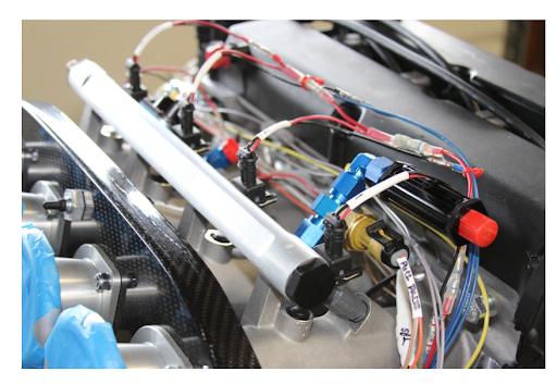
    Fig 6. Pressure sensor connection

    Which factors affect pressure sensor electrical connections?

    Several factors can influence pressure sensor electrical connections, impacting their performance, reliability, and accuracy:

    1. Cable Quality and Type:

  • Cable Material: The quality and type of cables used for connections can affect signal transmission and insulation, impacting the sensor's performance.
  • Shielding: Shielded cables help mitigate electromagnetic interference (EMI), preserving signal integrity in noisy environments.
  • 2. Cable Length and Routing:
  • Length: Longer cables can introduce signal degradation, affecting accuracy. Proper routing to avoid interference and signal loss is crucial.
  • Bending and Stress: Overbending, stress, or strain on cables can compromise insulation and lead to connection issues.
  • 3. Connectors and Termination:
  • Connector Quality: High-quality connectors ensure secure and reliable connections, preventing signal loss or intermittent connections.
  • Termination Integrity: Proper termination of cables and connectors is essential for signal transmission and reliability.
  • 4. Environmental Factors:
  • Temperature and Humidity: Extremes in temperature or humidity can affect cable insulation and connector integrity.
  • Chemical Exposure: Exposure to chemicals or corrosive substances can degrade cable materials or connectors.
  • 5. Grounding and Noise:
  • Grounding Practices: Inadequate or improper grounding can introduce noise, affecting signal quality.
  • Electrical Noise: External electrical noise sources or electromagnetic fields can interfere with signal transmission.
  • 6. Electrical Compatibility:
  • Voltage and Current: Ensuring the sensor's electrical requirements match the power supply's capabilities is crucial for proper operation.
  • Signal Conditioning: Consideration of signal conditioning devices or amplifiers to boost weak signals or minimize noise interference.
  • 7. Installation and Maintenance:
  • Proper Installation: Following manufacturer guidelines during installation helps maintain electrical connections' integrity.
  • Regular Maintenance: Periodic checks for cable wear, connector corrosion, or insulation damage ensure continued reliability.
  • 8. Manufacturer Specifications:
  • Manufacturer Recommendations: Adhering to specific recommendations and guidelines provided by the sensor manufacturer is critical for optimal electrical connections.
  • Compatibility with System: Ensuring the sensor's electrical specifications align with the overall system's requirements for seamless integration.
  • Considering these factors and implementing proper installation practices can ensure reliable and accurate electrical connections for pressure sensors, contributing to optimal sensor performance and longevity.

    Are there any points to be considered regarding the electrical connection of the pressure sensor in dangerous areas?

    Absolutely, electrical connections for pressure sensors in hazardous or dangerous areas require special attention and adherence to stringent safety protocols. Here are key points to consider:

    Hazardous Area Classification:

  • Understand Zone Classification: Identify the specific hazardous area classification (Zone 0, Zone 1, Zone 2, etc.) based on the presence and type of potentially explosive or hazardous substances.
  • Compliance with Regulations: Ensure that all electrical components, including pressure sensor connections, comply with relevant hazardous area regulations (ATEX, IECEx, NEC, etc.).
  • Explosion Protection Measures:
  • Intrinsically Safe (IS) Components: Use intrinsically safe or explosion-proof components certified for use in hazardous areas to prevent sparks or ignition sources.
  • Protection Techniques: Employ protection techniques like encapsulation, explosion-proof enclosures, or barriers to prevent potential ignition in the presence of flammable substances.
  • Selection of Components:
  • Certified Equipment: Choose pressure sensors and associated electrical components specifically designed and certified for hazardous area use.
  • Temperature and Ratings: Ensure that selected components can operate within the temperature and environmental ratings specified for the hazardous area.
  • Installation Practices:
  • Qualified Personnel: Only trained and certified personnel should handle installation, ensuring compliance with safety standards and regulations.
  • Proper Sealing: Seal cable entry points, connectors, and enclosures effectively to prevent the ingress of hazardous substances or gases.
  • Grounding and Bonding:
  • Effective Grounding: Implement proper grounding techniques to minimize the risk of static discharge or electrical arcs that could ignite hazardous substances.
  • Bonding Connections: Use bonding conductors to equalize electrical potentials between different components, reducing the risk of sparking.
  • Regular Inspections and Maintenance:
  • Scheduled Inspections: Conduct periodic inspections and maintenance checks to ensure the integrity of electrical connections, cables, and enclosures within hazardous areas.
  • Documentation: Maintain detailed records of installations, inspections, and maintenance activities as per regulatory requirements.
  • Compliance and Certifications:
  • Third-Party Certifications: Ensure all components and installations comply with relevant certifications and standards applicable to hazardous environments.
  • Consult Experts: Seek guidance from certified professionals or experts experienced in hazardous area installations for proper adherence to safety protocols.
  • Emergency Procedures:
  • Emergency Plans: Establish clear emergency procedures in case of incidents, including shutdown protocols and evacuation plans specific to hazardous area installations.
  • Training: Conduct regular training sessions for personnel working in hazardous areas, ensuring they understand safety protocols and emergency response.
  • Adhering to these stringent safety measures and regulations is critical when dealing with electrical connections for pressure sensors in hazardous areas. Prioritizing safety protocols helps mitigate risks and ensures safe operation within potentially explosive or dangerous environments.

    Conclusion

    When it comes to electrical connections for pressure sensors, attention to detail and adherence to specific guidelines are paramount. Proper installation, selection of appropriate cables, connectors, and following manufacturer recommendations ensure optimal performance and reliability. Factors like cable quality, length, environmental conditions, and grounding significantly impact signal integrity.

    Additionally, in hazardous areas, stringent safety measures, compliance with regulations, and specialized equipment become imperative to prevent potential hazards. Intrinsically safe components, proper grounding, and compliance with hazardous area classifications are essential in such environments.

    Regular inspections, maintenance, and adherence to safety standards play a pivotal role in sustaining the efficiency and safety of pressure sensor electrical connections. By prioritizing safety, following best practices, and staying informed about specific sensor models or hazardous area requirements, one can establish reliable and secure electrical connections for pressure sensors across diverse applications.

    To recap

    1. What types of electrical connections are common for pressure sensors?

    Common connections include analog (voltage or current) outputs, digital communication protocols (I2C, SPI), and Wheatstone bridge configurations.

    2. How do I identify the correct wiring configuration for a pressure sensor?

    Refer to the sensor's datasheet or manual for detailed wiring diagrams and pinout information provided by the manufacturer.

    3. Can I use standard electrical cables for connecting a pressure sensor?

    It's recommended to use cables specified by the sensor's manufacturer to ensure proper insulation and signal integrity.

    4. What precautions should I take when connecting a pressure sensor to an electrical circuit?

    Ensure power is off, use insulated tools, check polarity, and securely tighten connections to prevent hazards or signal disruptions.

    5. Are there specific grounding requirements for pressure sensors?

    Yes, proper grounding is crucial. Follow manufacturer guidelines for effective grounding to minimize electrical noise and ensure safety.

    6. How can cable length impact the performance of a pressure sensor?

    Longer cables may introduce signal degradation, leading to accuracy issues or signal interference due to increased resistance and capacitance.

    7. What factors affect pressure sensor electrical connections?

    Cable quality, environmental conditions, grounding, connector integrity, and compliance with specifications significantly impact electrical connections.

    8. What should be considered when connecting a pressure sensor in hazardous areas?

    Adherence to hazardous area classifications, using intrinsically safe components, proper sealing, and compliance with safety regulations are vital.

    9. How can I troubleshoot electrical issues with pressure sensor connections?

    Start with visual inspections, use testing equipment like multimeters, check grounding, and refer to manufacturer guidelines for troubleshooting steps.

    10. Where can I find detailed information about pressure sensor electrical connections for a specific model or brand?

    Detailed information is available in the sensor's datasheet, manuals, manufacturer's website, technical support, and industry forums related to instrumentation.

    References

    https://www.pressuresensor.org" rel="nofollow"/pressure-sensor-correct-wiring.html

    https://www.eastsensor.com" rel="nofollow"/blog/pressure-sensor-electrical-connection/

    https://instrumentationtools.com" rel="nofollow"/pressure-transmitter-circuit/

    https://support.smart-maic.com" rel="nofollow"/en/knowledge-bases/2/articles/151-d105-connecting-the-pressure-sensor

    https://junkyardzetec.com/fuel-pressure-sensor-placement-and-wiring/

    6th Jan 2024

    Recent Posts