

Beyond the Surface: The Inner Workings of a Pressure Transmitter
Imagine a world where the unseen forces of pressure are harnessed, measured, and transformed into valuable insights. In the heart of industries and systems, pressure transmitters serve as the sentinel guardians, translating the language of pressure into the realm of electronics. These remarkable devices bridge the tangible world with the digital, enabling us to understand, control, and optimize processes with precision.
Pressure transmitters are the unsung heroes of countless applications, from ensuring the safety of towering industrial machinery to fine-tuning the comfort of our indoor environments. They possess the power to convert the squeeze of a hydraulic system, the flow of gases, or the weight of a liquid column into intricate electrical signals. These signals, after a journey of transformation and enhancement, whisper valuable information about processes, from the movement of fluids deep underground to the operation of critical medical equipment.
Beyond their functional prowess, pressure transmitters weave together the threads of engineering, physics, and technology. Each type of sensor element, whether a piezoresistive strain gauge, a piezoelectric crystal, or a capacitive plate, brings its unique magic to this symphony of measurement. The marriage of these elements with sophisticated signal conditioning, microcontrollers, and power supplies transforms pressure's touch into tangible data that drives informed decisions.
As we delve into the intricate workings of pressure transmitters, we unearth a world of science and innovation. From the careful calibration that ensures accuracy to the elegant dance of microcontrollers orchestrating signal processing, every component plays a pivotal role. These devices cater to a diverse array of industries - from the relentless energy sector to the precision-driven realms of healthcare and beyond.
Join us on a journey into the heart of pressure transmitters, where the subtle whispers of pressure are translated into a language that modern industries understand. Here, the hidden forces are made visible, empowering us to navigate a world where measurement is key and accuracy reigns supreme.
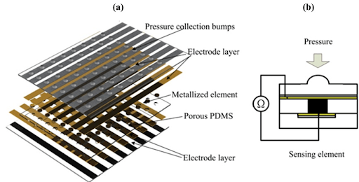
Fig 1. Pressure sensing element
What is a pressure transmitter?
A pressure transmitter is a device used to measure and convert the pressure of a fluid (liquid or gas) into an electrical signal. This electrical signal can then be utilized for various purposes such as monitoring, control, data logging, and automation in industrial processes and applications.
The pressure transmitter consists of several key components:
- Pressure Sensor: This is the primary component that detects the pressure of the fluid. Depending on the design and application, different types of pressure sensors can be used, such as strain gauge, piezoelectric, capacitive, and resonant sensors. These sensors are designed to deform or generate an electrical signal in response to changes in pressure.
- Transducer: The pressure sensor is connected to a transducer that converts the mechanical deformation or generated signal from the pressure sensor into an electrical signal, usually a voltage or current signal. This signal is proportional to the pressure being measured.
- Signal Conditioning Circuitry: The raw electrical signal from the transducer might require conditioning to make it more accurate, stable, and suitable for processing. This circuitry may include amplification, filtering, and temperature compensation to account for environmental factors that can affect the accuracy of the measurement.
- Output Interface: The conditioned electrical signal is sent to an output interface that converts it into a standardized signal for communication and data transfer. Typical output signals include analog signals (such as 4-20 mA current loop or 0-10 V voltage) and digital signals (such as MODBUS or HART protocols).
- Enclosure: Pressure transmitters are typically housed in a protective enclosure that shields sensitive internal components from environmental factors like moisture, dust, and temperature variations. The enclosure also provides mounting options for easy installation.
Pressure transmitters are used in a wide range of industries and applications, including manufacturing, oil and gas, chemical processing, pharmaceuticals, HVAC systems, aerospace, automotive, and more. They play a crucial role in process control, safety monitoring, equipment protection, and ensuring optimal performance in various industrial processes and systems.
What are the pressure transmitter's internal parts?
A pressure transmitter consists of several internal parts that work together to measure the pressure of a fluid and convert it into an electrical signal. The exact internal components can vary based on the design and manufacturer of the transmitter, but here are the common internal parts you might find in a pressure transmitter:
- Pressure Sensor: This is the core component that directly interacts with the fluid's pressure. Different types of pressure sensors can be used, including strain gauge, piezoelectric, capacitive, and resonant sensors. The sensor's mechanical deformation or electrical response due to pressure changes is the foundation of pressure measurement.
- Diaphragm: In many pressure transmitters, a diaphragm is used to transmit the pressure from the fluid to the pressure sensor. The diaphragm is a flexible membrane that deforms in response to pressure variations. It acts as the interface between the liquid and the pressure sensor, allowing the pressure to be accurately transmitted while isolating the sensor from the fluid.
- Transducer: The pressure sensor's mechanical response or electrical signal needs to be transformed into a usable electrical signal for output. The transducer converts this signal and often includes components like strain gauges, piezoelectric crystals, or other mechanisms that respond to the sensor's input.
- Signal Conditioning Circuitry: This circuitry processes and conditions the raw signal from the transducer to improve accuracy, and stability, and compensate for environmental factors. It might involve amplification, filtering, and temperature compensation to ensure the output signal accurately represents the pressure being measured.
- Output Electronics: These electronics convert the conditioned signal into a standardized output signal. This can be an analog signal like a 4-20 mA current loop or a 0-10 V voltage, or a digital signal using protocols like MODBUS, HART, Profibus, etc.
- Microcontroller/Processor: Many modern pressure transmitters include a microcontroller or processor that manages the signal processing, calibration, and communication with external devices. It can also implement various algorithms for temperature compensation, linearity correction, and other advanced features.
- Enclosure: The internal components are housed within a protective enclosure. The enclosure shields the sensitive parts from environmental factors and provides mechanical protection. It usually has ports for fluid connection and mounting options for installation.
- Calibration Components: Pressure transmitters require calibration to ensure accurate measurement. Calibration components, such as trim pots or digital calibration circuits, are often present to allow adjustments to the sensor's output signal to match the actual pressure.
- Power Supply Components: Pressure transmitters require a power supply to operate. Internal components related to power supply regulation and distribution may be present to ensure the transmitter receives stable and appropriate power.
It's important to note that the specific design and components can vary among different pressure transmitter models and manufacturers. The goal of these internal parts is to accurately measure pressure, condition the signal, and provide a reliable output for integration into various industrial processes and control systems.
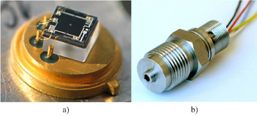
Fig 2. a) SP-9 sensing element mounted on a TO-5 housing, b) industrial pressure sensor based on the SP-9 sensing element
What is a pressure sensor?
A pressure sensor, also known as a pressure transducer or pressure transducer sensor, is a device designed to measure the pressure of a fluid (liquid or gas) and convert it into an electrical signal. Pressure sensors are commonly used in various industrial, commercial, and scientific applications to monitor and control pressure-related parameters.
Pressure sensors work on the principle that changes in pressure result in mechanical deformations or other measurable changes in certain materials. Different types of pressure sensors use various mechanisms to detect and convert pressure changes into electrical signals. Here are a few common types of pressure sensors:
- Strain Gauge Pressure Sensor: This type of sensor uses a strain gauge, which is a small piece of wire or foil that changes resistance when stretched or compressed. The strain gauge is bonded to a flexible diaphragm that deforms when subjected to pressure changes. The resistance change is then measured and converted into an electrical signal.
- Piezoelectric Pressure Sensor: Piezoelectric sensors use crystals or materials that generate a voltage when mechanically stressed or compressed. When pressure is applied, these materials produce an electric charge proportional to the applied pressure. This charge is converted into an electrical signal.
- Capacitive Pressure Sensor: Capacitive sensors utilize changes in capacitance between two conductive plates or surfaces. The spacing between the plates changes with pressure variations, leading to a change in capacitance. This change is then converted into an electrical signal.
- Resonant Pressure Sensor: Resonant sensors operate on the principle that the resonant frequency of a material changes with pressure. When pressure is applied, it alters the material's mechanical properties and consequently its resonant frequency. The frequency change is measured and converted to an electrical signal.
- Optical Pressure Sensor: Optical pressure sensors use light intensity changes to measure pressure-induced deformations. These sensors are based on the principle that the amount of light passing through or reflecting off a material changes with deformation, which is proportional to the applied pressure.
- Microelectromechanical Systems (MEMS) Pressure Sensor: MEMS pressure sensors are miniaturized devices that use microfabrication techniques to create tiny mechanical structures. These structures deform under pressure, and the resulting changes are detected using electronic components integrated into the same chip.
Pressure sensors are used in various industries and applications, including automotive, aerospace, medical devices, industrial automation, HVAC systems, and more. They play a crucial role in measuring and monitoring processes, controlling systems, ensuring safety, and optimizing performance in a wide range of environments. The type of pressure sensor chosen depends on factors such as the pressure range, accuracy requirements, operating conditions, and the specific application's demands.
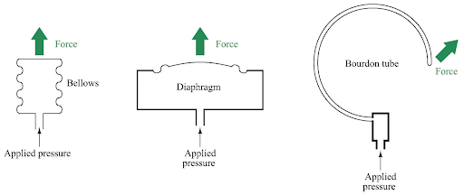
Fig 3. Different Pressure sensor element
How is a pressure sensor structure?
The structure of a pressure sensor can vary based on the type of sensor and its intended application. However, I can provide a general overview of the components and structure commonly found in a pressure sensor:
- Diaphragm or Sensing Element: The diaphragm is a flexible membrane that directly interacts with the pressure being measured. It deforms under the influence of pressure changes. Different materials and shapes are used for diaphragms depending on the pressure range and application. The diaphragm's deformation is the primary mechanism that enables pressure measurement.
- Strain Gauges, Piezoelectric Crystals, or Capacitive Plates: These are the elements that detect the deformation of the diaphragm and convert it into an electrical signal. The choice of technology depends on the sensor type. For example, strain gauges measure the change in resistance due to deformation, piezoelectric crystals generate electric charge, and capacitive plates measure changes in capacitance.
- Enclosure or Casing: The sensing element and associated electronics are housed within a protective enclosure or casing. This casing shields the sensitive components from environmental factors such as moisture, dust, and mechanical damage. The casing is often designed to allow fluid pressure to be applied to the diaphragm while isolating the internal components.
- Signal Conditioning Circuitry: Pressure sensors often include circuitry to condition the raw signal from the sensing element. This may involve amplification, filtering, temperature compensation, and linearization to ensure that the output accurately represents the applied pressure.
- Output Electronics: These components convert the conditioned signal into a standardized output signal that can be easily interfaced with other devices or systems. Common output signals include analog voltage (0-10 V) or current (4-20 mA), as well as digital communication protocols like I2C, SPI, HART, and more.
- Electrical Contacts or Terminals: These are the points where electrical connections are made to the sensor. They allow the sensor to receive power and transmit the output signal to external systems.
- Reference Chamber (For Differential Pressure Sensors): Some pressure sensors, particularly differential pressure sensors, have a reference chamber on the opposite side of the diaphragm. This chamber provides a reference pressure against which the pressure on the diaphragm is measured.
- Sealing Mechanism: To ensure that the diaphragm maintains contact with the fluid being measured while preventing leaks, pressure sensors often include a sealing mechanism. This could be in the form of O-rings or other sealing materials.
- Temperature Compensation Elements: Pressure measurements can be affected by temperature changes. Some pressure sensors incorporate temperature compensation components or algorithms to correct temperature-related variations in the output signal.
It's important to note that the specific structure and components can vary depending on the pressure sensor's type, design, and intended application. Manufacturers may innovate and customize these components to suit different industrial and commercial needs.
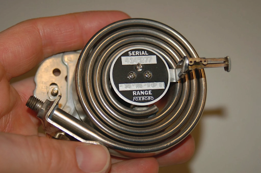
Fig 4. spiral bourdon tube
What features should the sensing element of the pressure sensor have?
The sensing element is a critical component of a pressure sensor, as it directly interacts with the pressure being measured and converts that pressure into an electrical signal. The features and characteristics of the sensing element are crucial to the accuracy, sensitivity, and reliability of the pressure sensor. Here are some key features that a well-designed sensing element of a pressure sensor should ideally have:
- High Sensitivity: The sensing element should be able to detect even small changes in pressure with high sensitivity. This is important for accurately measuring pressure variations, especially in applications where precise pressure control is essential.
- Linearity: The relationship between the applied pressure and the resulting electrical signal should be linear. In other words, the change in output signal should be directly proportional to the change in pressure. This helps in accurate and consistent pressure measurement.
- Low Hysteresis: Hysteresis refers to the difference in output readings when the pressure is increased and then decreased along the same pressure path. A good sensing element should exhibit minimal hysteresis, ensuring that the output signal accurately follows pressure changes in both directions.
- Wide Operating Range: The sensing element should be capable of operating over a wide range of pressure values, from very low pressures to high pressures. This ensures the sensor's versatility across different applications.
- Fast Response Time: In applications where pressure changes rapidly, such as dynamic industrial processes, the sensing element should have a fast response time to accurately capture sudden pressure fluctuations.
- Mechanical Stability: The sensing element should be mechanically stable, and capable of maintaining its integrity and accuracy over time. It should withstand pressure cycles, mechanical shocks, and other stresses without significant degradation.
- Temperature Compensation: Pressure sensor measurements can be affected by temperature variations. A well-designed sensing element might incorporate temperature compensation mechanisms to account for these effects and provide accurate readings across a wide temperature range.
- Low Power Consumption: Especially for applications where power efficiency is important, the sensing element should consume minimal power while still providing accurate and reliable measurements.
- Durability and Corrosion Resistance: The sensing element should be made from materials that are resistant to corrosion and environmental factors, especially in applications where the sensor might come into contact with aggressive chemicals or harsh conditions.
- Low Drift: Drift refers to the gradual change in the sensor's output signal over time, even when the pressure remains constant. A good sensing element should exhibit minimal drift to ensure long-term measurement stability.
- Low Interference: The sensing element should be designed to minimize interference from external factors such as electromagnetic fields, vibrations, and other environmental disturbances.
- Minimal Mechanical Load on the Measured System: Some applications require minimal impact on the system being measured. The sensing element should impose as little mechanical load as possible to avoid altering the pressure characteristics of the system.
These features contribute to the overall performance, accuracy, and reliability of the pressure sensor. Different sensor technologies and designs will emphasize different aspects, and the selection of a sensing element depends on the specific requirements of the application.

Fig 5. Sensor elements
What is the function of the sensor element in pressure transmitters?
The sensor element in a pressure transmitter is the core component responsible for directly interacting with the pressure being measured and converting it into an electrical signal that can be processed, transmitted, and interpreted. The sensor element's function is crucial to the accuracy and reliability of pressure measurements. Here's how the sensor element works within a pressure transmitter:
- Pressure Interaction: The sensor element is designed to deform or respond to changes in pressure. When pressure is applied to the sensor element, it undergoes mechanical deformation, such as stretching, bending, or deflection. This deformation is the result of the pressure exerting force on the sensor element's surface.
- Deformation Mechanisms: Different types of pressure sensor technologies use various deformation mechanisms. For example:
- Strain Gauge: Strain gauges are bonded to the surface of the sensor element. As the element deforms, the strain gauges experience a change in resistance, which is directly proportional to the pressure-induced deformation.
- Piezoelectric Crystal: Piezoelectric crystals generate an electric charge when subjected to mechanical deformation. The applied pressure causes the crystal to deform, producing an electric signal.
- Capacitive Plates: Capacitive pressure sensors consist of two parallel plates separated by a dielectric material. The deformation of the sensor element changes the distance between the plates, altering the capacitance and generating an electrical signal.
- Signal Generation: The deformation-induced change in the sensor element's properties, such as resistance, capacitance, or electric charge, results in the generation of an electrical signal. This signal is proportional to the applied pressure.
- Raw Signal: The generated electrical signal from the sensor element is often small and not directly usable for measurement. It needs to be conditioned and processed before being transmitted or interpreted.
- Signal Conditioning: The raw signal is sent to the signal conditioning circuitry, which may involve amplification, filtering, linearization, and temperature compensation. The conditioning circuitry prepares the signal for accurate measurement and transmission.
- Conversion to Standard Output: Once conditioned, the signal is further processed to match the desired output format, such as analog voltage or current, or digital communication protocols like HART, MODBUS, etc.
- Temperature Compensation: In some pressure transmitters, the sensor element may be affected by temperature changes, leading to variations in the signal. Temperature compensation techniques are applied to correct for these effects and ensure accurate pressure measurement.
- Calibration: The sensor element's behavior might exhibit some variations due to manufacturing tolerances and material properties. Calibration adjustments are made to align the sensor's response with a known reference pressure source, ensuring accuracy across the pressure range.
- Environmental Isolation: The sensor element is often enclosed within protective materials to shield it from environmental factors like moisture, dust, and temperature fluctuations. This isolation maintains the element's performance over time.
- Application Variability: Different sensor technologies and designs are suited for various pressure ranges, fluid types, and applications. The choice of sensor element depends on the specific requirements of the pressure measurement task.
In summary, the sensor element in a pressure transmitter acts as the interface between the applied pressure and the electrical signal. Its ability to accurately convert pressure changes into measurable electrical responses forms the foundation for reliable pressure measurement and control in various industrial and commercial applications.
Which type of sensor element is used in pressure transmitters?
Pressure transmitters use various types of sensor elements, each based on different principles of operation. The choice of sensor element depends on factors such as the pressure range, application requirements, accuracy, environmental conditions, and cost considerations. Here are some common types of sensor elements used in pressure transmitters:
- Description: Strain gauge pressure sensors use the piezoresistive effect, where the resistance of material changes with applied mechanical strain.
- Operation: A strain gauge is bonded to a flexible diaphragm. As pressure changes, the diaphragm deforms, causing strain in the gauge and altering its resistance. This change in resistance is converted into an electrical signal.
- Advantages: High accuracy, good linearity, and stability; suitable for various pressure ranges; rugged construction.
- Applications: General industrial applications, automotive, process control.
- Description: Piezoelectric pressure sensors use crystals that generate an electric charge when subjected to mechanical stress.
- Operation: Pressure deforms the crystal, generating an electric charge across its surface. This charge is converted into a voltage signal.
- Advantages: Fast response time, no need for power during measurement, high-frequency response.
- Applications: Dynamic pressure measurements, impact measurements, acoustic applications.
- Description: Capacitive pressure sensors use changes in capacitance between two plates to measure pressure-induced deformation.
- Operation: Pressure-induced deformation alters the distance between the plates, changing the capacitance. This change is converted into an electrical signal.
- Advantages: High accuracy, low hysteresis, low power consumption.
- Applications: Industrial and HVAC applications, medical devices, aerospace.
- Description: Resonant silicon pressure sensors use the change in the resonant frequency of a micro-machined resonator due to applied pressure.
- Operation: Pressure changes the mechanical properties of the resonator, altering its resonant frequency. This frequency shift is converted into an electrical signal.
- Advantages: High sensitivity, low power consumption, small size.
- Applications: High-precision pressure measurement, medical devices, aerospace.
- Description: Optical pressure sensors use the interference of light to measure the deformation of a diaphragm due to pressure.
- Operation: Pressure changes the diaphragm's shape, affecting the path length of an optical beam. Interference patterns are analyzed to determine pressure.
- Advantages: High accuracy, and immunity to electromagnetic interference.
- Applications: Harsh environments, medical applications, aerospace.
- Description: Differential pressure capsules use two diaphragms that experience pressure difference to measure differential pressure.
- Operation: Pressure differences between the diaphragms create a mechanical deflection that is converted into an electrical signal.
- Advantages: Suitable for measuring pressure differences, and accurate differential pressure measurements.
- Applications: Flow measurement, level measurement, differential pressure applications.
- Description: Thin-film pressure sensors use thin-film resistors deposited on a substrate to measure pressure-induced strain.
- Operation: Pressure causes the thin-film resistors to change resistance due to mechanical deformation.
- Advantages: Compact size, fast response, low power consumption.
- Applications: Automotive, medical devices, industrial automation.
Strain Gauge (Piezoresistive):
Piezoelectric Crystal:
Capacitive:
Resonant Silicon (Piezoelectric Resonator):
Optical:
Differential Pressure Capsule:
Thin-Film:
The choice of sensor element depends on the specific requirements of the application, such as pressure range, accuracy, response time, environmental conditions, and cost considerations. Each type of sensor element has its advantages and limitations, and selecting the most suitable one ensures optimal performance and reliability of the pressure transmitter.
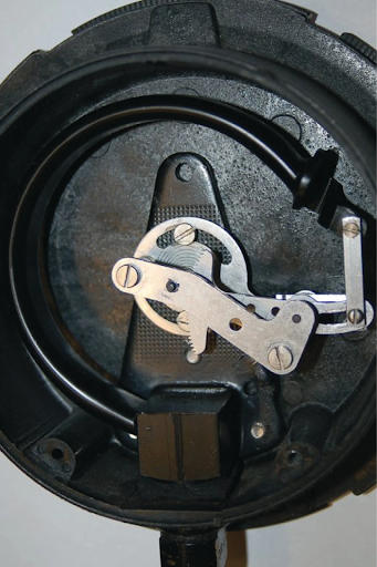
Fig 6. C-tube pressure gauge mechanism
How should the Diaphragm be in a pressure transmitter?
The diaphragm is a crucial component in a pressure transmitter, as it is responsible for transmitting the applied pressure to the sensing element, which then converts it into an electrical signal. The design of the diaphragm is essential to ensure accurate and reliable pressure measurement. Here are some considerations for designing the diaphragm in a pressure transmitter:
- Material Selection: Choose a material for the diaphragm that is compatible with the fluid being measured and the environmental conditions of the application. The material should be corrosion-resistant, mechanically stable, and able to withstand temperature variations.
- Flexibility: The diaphragm should be flexible enough to deform under pressure changes. The degree of flexibility depends on the pressure range the transmitter is designed to measure. Thicker diaphragms might be used for higher pressure ranges, while thinner diaphragms are suitable for lower pressures.
- Size and Shape: The size and shape of the diaphragm influence its sensitivity and response to pressure changes. The diaphragm should be designed to ensure uniform deformation across its surface and to minimize stress concentrations that could affect accuracy.
- Support Structure: Depending on the pressure range and application, the diaphragm might require a support structure to prevent excessive deformation or distortion. This structure should not significantly impact the diaphragm's ability to transmit pressure accurately.
- Diaphragm Sealing: Ensure that the diaphragm is properly sealed to the rest of the transmitter's structure to prevent fluid leaks. Effective sealing is essential to maintain the integrity of pressure measurement and to protect internal components from the environment.
- Reference Chamber (Differential Pressure Transmitters): In differential pressure transmitters, where the pressure on both sides of the diaphragm is measured, a reference chamber is often used on the opposite side of the diaphragm. This chamber provides a known reference pressure against which the measured pressure is compared.
- Avoiding Overloading: The diaphragm design should prevent overloading, which could lead to permanent deformation or damage. This is particularly important for applications where pressure spikes or sudden changes are common.
- Temperature Compensation: Depending on the application, the diaphragm design might need to incorporate temperature compensation mechanisms to account for thermal expansion and contraction effects on the material.
- Mechanical Stability: The diaphragm should be able to maintain its mechanical integrity over time, even after many pressure cycles. It should not exhibit fatigue or creep under prolonged exposure to pressure.
- Mounting and Attachment: The diaphragm should be securely attached to the rest of the transmitter's structure while still allowing for efficient pressure transmission. Proper mounting ensures that the diaphragm's deformation accurately corresponds to the applied pressure.
- Environmental Considerations: Consider the operating environment of the pressure transmitter, including factors such as temperature, humidity, and exposure to chemicals. The diaphragm design should be able to withstand these conditions without compromising its performance.
Overall, the diaphragm's design should be a balance between flexibility, mechanical stability, and sensitivity, tailored to the specific pressure range and requirements of the pressure transmitter's application.
What are the features of a Transducer in a pressure transmitter?
A transducer in a pressure transmitter is a crucial component that takes the mechanical deformation or signal generated by the pressure-sensing element (often a diaphragm) and converts it into an electrical signal that can be processed, transmitted, and utilized for measurement, control, or monitoring purposes. Here are the key features and characteristics that a transducer in a pressure transmitter should ideally possess:
- Signal Conversion: The primary function of the transducer is to convert the mechanical deformation or generated signal from the sensing element (such as strain gauge, piezoelectric crystal, etc.) into an electrical signal that can be measured and processed.
- Amplification: In some cases, the electrical signal generated by the sensing element might be weak or low-level. The transducer may incorporate amplification circuitry to enhance the signal strength while maintaining accuracy.
- Linearity: The transducer's response should be linear, meaning that the change in the output signal should be directly proportional to the change in pressure. Linearity ensures an accurate representation of pressure variations.
- Low Noise: The transducer should minimize the introduction of electrical noise into the signal, which could distort measurements and affect accuracy.
- Accuracy: The transducer's output should closely match the actual pressure being measured. High accuracy is vital for applications that require precise pressure control or measurement.
- Temperature Compensation: Pressure measurements can be affected by temperature changes. The transducer might include temperature compensation circuitry to correct for temperature-related variations in the output signal.
- Frequency Response: The transducer's response time should be appropriate for the application. In fast-changing pressure environments, a fast frequency response is crucial to capture rapid pressure fluctuations accurately.
- Stability: The transducer's performance should remain consistent over time, even after repeated pressure cycles and extended use.
- Low Distortion: The transducer should minimize signal distortion to ensure that the output accurately represents the pressure input without introducing unwanted artifacts.
- Low Power Consumption: Especially in applications where power efficiency is essential, the transducer should consume minimal power while still providing reliable signal conversion.
- Digital Signal Processing (if applicable): Some pressure transmitters incorporate digital signal processing within the transducer. This can enable advanced features such as digital communication protocols (HART, MODBUS, etc.), calibration adjustments, and diagnostic capabilities.
- Compatibility: The transducer's output should be compatible with the communication and control systems used in the application. This might involve providing analog voltage or current signals, or digital signals, as required.
- Isolation: In applications where electrical isolation is important to prevent interference or potential safety hazards, the transducer might incorporate isolation mechanisms.
- Durability and Reliability: The transducer should be designed to withstand the conditions of the application, including mechanical stresses, temperature variations, and exposure to harsh environments.
- Compactness and Integration: Pressure transmitters often need to be compact and easily integrated into systems. The transducer's design should facilitate this integration.
- Calibration Adjustments: Some pressure transmitters allow for calibration adjustments to fine-tune the output signal, ensuring optimal accuracy.
Overall, the transducer's features contribute to the overall performance and functionality of the pressure transmitter. Different transducer designs and technologies emphasize different aspects, and the selection of a transducer depends on the specific requirements of the application.
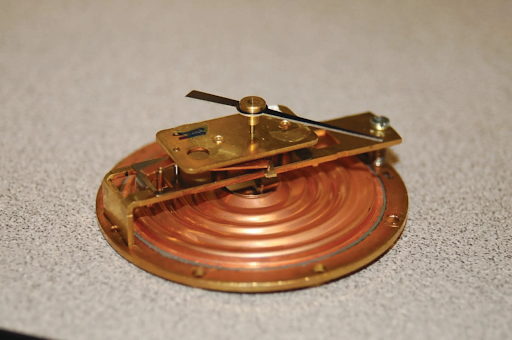
Fig 7. A small pressure gauge using a brass diaphragm as the sensing element
What important factors to choose the proper Signal Conditioning Circuitry for pressure transmitters?
Selecting the proper signal conditioning circuitry for a pressure transmitter is crucial for ensuring accurate and reliable pressure measurements. The signal conditioning circuitry processes the raw signal from the sensing element and prepares it for transmission and interpretation. Here are important factors to consider when choosing signal conditioning circuitry for a pressure transmitter:
- Pressure Range and Resolution: The circuitry should be suitable for the pressure range you intend to measure. Different pressure ranges might require different levels of amplification, filtering, and signal conditioning to achieve the desired resolution and accuracy.
- Accuracy and Linearity: Consider the required accuracy for your application. The signal conditioning circuitry should maintain linearity and minimize any nonlinear effects that might introduce errors in the measurement.
- Amplification: Determine if the raw signal from the sensing element needs amplification to match the input range of the data acquisition or control system. Choose an amplifier with appropriate gain to ensure the signal is well-scaled for accurate measurement.
- Filtering: If the raw signal contains noise or unwanted high-frequency components, filtering might be necessary to remove these disturbances. Choose filters that match the noise characteristics of your application while preserving the essential pressure signal.
- Temperature Compensation: Depending on the application's temperature variations, the circuitry might need to include temperature compensation components to correct for temperature-induced changes in the output signal.
- Response Time: Consider the required response time of the pressure transmitter. Fast-changing pressure conditions may necessitate a faster response time in the signal conditioning circuitry to accurately capture pressure fluctuations.
- Power Consumption: Evaluate the power consumption of the signal conditioning circuitry, especially in applications where power efficiency is crucial. Lower power consumption extends battery life in portable or remote installations.
- Digital vs. Analog Output: Decide whether you need a digital or analog output. Digital output can provide enhanced accuracy, noise immunity, and easier integration with digital systems. Analog output might be preferred for compatibility with existing analog control systems.
- Communication Protocols: If you're using digital output, consider the communication protocols that your system supports. Common protocols include HART, MODBUS, Profibus, and more.
- Calibration and Adjustment: Some signal conditioning circuits allow for calibration adjustments to fine-tune the output signal. Consider whether this capability is necessary for your application.
- Isolation: Depending on the application's electrical environment and safety considerations, isolation between the input (sensing element) and output (transmitter) sides might be necessary. Isolation protects against ground loops and interference.
- Environmental Conditions: Ensure the selected signal conditioning circuitry can operate reliably within the environmental conditions of the application, including temperature, humidity, and potential exposure to corrosive substances.
- EMC and EMI: Consider electromagnetic compatibility (EMC) and electromagnetic interference (EMI) standards and requirements for your application. The circuitry should be designed to minimize electromagnetic interference and pass EMC tests.
- Cost: Balancing performance with cost is essential. Choose a solution that meets your performance requirements without unnecessary overdesign.
- Integration with Sensing Element: Ensure that the signal conditioning circuitry is compatible with the specific sensing element and overall pressure transmitter design.
By carefully considering these factors, you can choose signal conditioning circuitry that optimally prepares the raw pressure signal for accurate measurement and reliable transmission in your pressure transmitter.
How can choose the best Output Electronics for a pressure transmitter?
Choosing the best output electronics for a pressure transmitter is crucial to ensure accurate signal transmission and compatibility with your application's requirements. The output electronics convert the conditioned signal from the transducer into a standardized output format that can be easily interfaced with other systems or devices. Here's how to choose the best output electronics for your pressure transmitter:
- Analog vs. Digital Output:
- Analog Output: Decide whether you need an analog output signal, such as a voltage (e.g., 0-10 V) or current (e.g., 4-20 mA) signal. Analog signals are commonly used in traditional control systems.
- Digital Output: If you require higher accuracy, noise immunity, and additional features like diagnostics, consider a digital output format, which can include protocols like HART, MODBUS, Profibus, and more.
- Application Requirements:
- Consider your application's requirements for accuracy, response time, and noise immunity. Some applications might demand a digital output for higher accuracy and better noise rejection, while others might be well-served by analog signals.
- Communication Protocols (if using Digital Output):
- If you opt for a digital output, choose a communication protocol that is compatible with your existing systems. Different protocols offer varying levels of data transmission rates and functionality.
- Integration with Control Systems:
- Ensure the chosen output format can be easily integrated into your control or monitoring system. Consider the compatibility of connectors, wiring, and input types.
- Resolution and Data Format (for Digital Output):
- If you choose a digital output, consider the resolution of the data and the format in which it's transmitted. Higher resolution can provide more accurate readings.
- Power Supply Compatibility:
- Confirm that the power supply requirements of the output electronics align with the available power sources in your application.
- Diagnostic Capabilities (for Digital Output):
- Some digital output protocols offer diagnostic capabilities, allowing you to monitor the health and performance of the pressure transmitter remotely. This can be valuable for predictive maintenance.
- Isolation and Grounding:
- Ensure that the output electronics provide adequate isolation and grounding to prevent interference and maintain signal integrity.
- Environmental Conditions:
- Consider the environmental conditions of your application, including temperature, humidity, and potential exposure to corrosive substances. The output electronics should be designed to withstand these conditions.
- EMC and EMI Compliance:
- Make sure the chosen output electronics meet electromagnetic compatibility (EMC) and electromagnetic interference (EMI) standards and requirements for your application.
- Ease of Installation and Maintenance:
- Choose output electronics that are easy to install, calibrate, and maintain. Clear documentation and user-friendly interfaces can simplify setup and troubleshooting.
- Cost-Effectiveness:
- Balance the features and performance of the output electronics with your budget constraints.
- Future Expandability:
- Consider the potential for future system expansions or upgrades. Choose output electronics that offer flexibility for integration with new technologies.
- Vendor Support and Reliability:
- Work with reputable manufacturers or suppliers that offer reliable products and provide good technical support if needed.
By carefully evaluating these factors and aligning them with your application's requirements, you can select the best output electronics for your pressure transmitter to ensure accurate and reliable signal transmission.
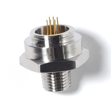
Fig 8. Pressure sensor
Explaining features of the Microcontroller/Processor of the pressure transmitter
The microcontroller or processor in a pressure transmitter plays a vital role in processing and managing the signals, data, and functionality of the device. Here are the key features and functions of the microcontroller/processor in a pressure transmitter:
- Signal Processing: The microcontroller processes the raw signal from the transducer and performs necessary calculations, such as amplification, linearization, and temperature compensation. This ensures that the output signal accurately represents the pressure being measured.
- Calibration and Adjustment: The microcontroller often includes the capability to calibrate and adjust the pressure transmitter's output. This might involve fine-tuning the signal to match known reference pressures or adjusting for variations in the sensing element's characteristics.
- Data Storage: The microcontroller can store calibration data, configuration settings, and other parameters. This is useful for maintaining calibration across power cycles or for storing specific calibration data for different pressure ranges.
- Digital Communication: Many pressure transmitters incorporate digital communication protocols, such as HART, MODBUS, or Profibus. The microcontroller manages the communication process, allowing the pressure transmitter to interact with other devices or systems.
- Diagnostic Functions: The microcontroller can implement diagnostic routines to monitor the health and performance of the pressure transmitter. It can detect faults, irregularities, or sensor drift, enabling predictive maintenance and troubleshooting.
- Temperature Compensation: The microcontroller can manage temperature compensation algorithms to correct for temperature-induced variations in the output signal. This is especially important for applications with varying temperature conditions.
- A/D Conversion: If the sensing element's output is analog and the signal conditioning is performed digitally, the microcontroller includes analog-to-digital converters (ADCs) to convert the analog signal into digital data for processing.
- Digital Filtering: The microcontroller can apply digital filters to the signal to reduce noise and interference, enhancing the accuracy of the pressure measurement.
- Power Management: The microcontroller manages power distribution and consumption within the pressure transmitter, optimizing energy usage and extending battery life in battery-powered devices.
- User Interface: If the pressure transmitter has a user interface (such as a display or buttons), the microcontroller manages user interactions, displays pressure readings, and responds to user commands.
- Protocol Handling: For pressure transmitters with digital communication capabilities, the microcontroller handles protocol-specific tasks, such as framing data, error checking, and responding to queries from external devices.
- Safety and Redundancy: In critical applications, redundant microcontrollers can be employed to enhance reliability and safety. If one microcontroller fails, the redundant one takes over to ensure continuous operation.
- Firmware Updates: The microcontroller allows for firmware updates to enhance features, fix bugs, or adapt to changing requirements. This is particularly important for long-term device support.
- Clock and Timing: The microcontroller provides accurate timing for signal processing, data acquisition, and communication tasks.
- Integration with External Systems: The microcontroller facilitates seamless integration of the pressure transmitter into larger control, monitoring, or automation systems.
- Security: If required, the microcontroller can implement security features to protect sensitive data and prevent unauthorized access to the pressure transmitter's settings or communication.
The microcontroller's features and capabilities greatly influence the pressure transmitter's performance, flexibility, and functionality. The choice of microcontroller depends on the complexity of the pressure transmitter's requirements and the desired features for your specific application.
What is an Enclosure in a pressure transmitter?
An enclosure in a pressure transmitter refers to the protective housing or casing that contains and shields the internal components of the transmitter from environmental factors such as moisture, dust, temperature variations, and mechanical damage. The enclosure is an important component that ensures the proper functioning and longevity of the pressure transmitter in various operating conditions and environments.
Here are some key aspects of an enclosure in a pressure transmitter:
- Physical Protection: The primary purpose of the enclosure is to provide physical protection to the sensitive internal components of the pressure transmitter. It shields the components from potential mechanical damage, impact, and wear and tear.
- Environmental Protection: The enclosure prevents environmental factors like moisture, dust, dirt, and other contaminants from entering the pressure transmitter. This protection is particularly crucial in industrial environments where the transmitter might be exposed to harsh conditions.
- Temperature Control: Enclosures can be designed with insulation or thermal management features to protect the internal components from extreme temperatures or rapid temperature changes that could affect the accuracy and performance of the pressure measurement.
- Chemical Resistance: In applications where the pressure transmitter might come into contact with corrosive substances, the enclosure can be made from materials that are resistant to chemical damage.
- Mounting and Installation: The enclosure typically includes mounting options that allow the pressure transmitter to be securely installed in various orientations, whether vertically, horizontally, or on a surface. This makes installation convenient and adaptable to different setups.
- Fluid Sealing: For pressure transmitters that are directly in contact with the fluid being measured, the enclosure might include sealing mechanisms to prevent fluid leakage into the internal components.
- Cable Entry Points: The enclosure provides entry points for cables and wires that connect to the pressure transmitter's internal electronics. These entry points should be properly sealed to maintain the enclosure's environmental protection.
- Ventilation and Cooling: Some enclosures might include ventilation or cooling features to dissipate heat generated by the internal components, ensuring stable operation.
- Transparent Windows (Optional): In pressure transmitters with displays or indicators, the enclosure might have transparent windows that allow users to view the display without compromising the protective integrity of the enclosure.
- Certifications: Depending on the industry and application, enclosures might need to adhere to specific standards or certifications (such as NEMA or IP ratings) to ensure adequate protection against specific environmental conditions.
- Access and Maintenance: The enclosure should allow for easy access to internal components when maintenance or adjustments are required, without compromising the enclosure's protective functions.
- Size and Form Factor: The enclosure's size and shape are designed to accommodate the pressure transmitter's internal components while fitting within the constraints of the installation environment.
Overall, the enclosure serves as a barrier that shields the pressure transmitter from external elements that could compromise its performance and accuracy. The choice of enclosure design and materials depends on the specific application's environmental requirements and the level of protection needed.
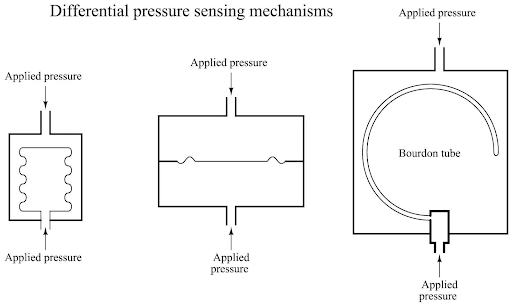
Fig 9. Differential pressure sensor element mechanism
How are the Calibration Components of pressure transmitters?
Calibration components in a pressure transmitter are elements that allow for adjustments to the transmitter's output signal, ensuring that it accurately represents the applied pressure. Calibration is a crucial step in the manufacturing and maintenance of pressure transmitters to guarantee their accuracy and reliability. Here's an overview of the calibration components and their role:
- Trim Pots (Potentiometers): These are adjustable resistors that can be tuned to fine-tune the output signal of the pressure transmitter. Trim pots are commonly used to calibrate the zero and span of the transmitter's output. The zero adjustment aligns the output signal with a reference value when there is no applied pressure. The span adjustment sets the slope of the output signal to match the full-scale pressure range.
- Digital Calibration Circuits: In modern pressure transmitters with digital processing capabilities, calibration adjustments can be performed digitally using software-controlled circuits. These circuits allow for precise adjustments of the output signal without the need for physical trim pots.
- Calibration Registers (Digital Transmitters): Digital pressure transmitters often have calibration registers that store calibration coefficients or parameters. These registers are used to adjust the output signal digitally and compensate for variations in the sensing element's characteristics.
- Factory Calibration: Pressure transmitters are often calibrated at the factory before being shipped to customers. Factory calibration involves carefully adjusting the transmitter's internal components to ensure accurate measurements across the specified pressure range.
- User Calibration: Some pressure transmitters provide the ability for users to perform field calibration. This might involve accessing calibration menus through a user interface, adjusting trim pots, or using calibration software for digital transmitters.
- Calibration Standards: Calibration components are adjusted against known calibration standards or reference pressure sources to ensure accuracy. Calibration standards might include precision pressure gauges or reference pressure chambers.
- Calibration Procedures: Pressure transmitter manufacturers provide calibration procedures and guidelines to assist users in calibrating the transmitter correctly. These procedures include step-by-step instructions for adjusting trim pots or digital calibration parameters.
- Traceability: Calibration processes often involve traceability, which means that the calibration is linked to a known and standardized measurement system. This ensures that the calibration is reliable and can be verified.
- Calibration Certificates: In some industries, pressure transmitters come with calibration certificates that document the calibration process, the results, and any adjustments made. These certificates assure the transmitter's accuracy.
- Regular Recalibration: Over time, the accuracy of pressure transmitters can drift due to environmental factors or wear. Regular recalibration ensures that the transmitter continues to provide accurate measurements. The frequency of recalibration depends on the application's requirements.
- Calibration Labs: For critical applications, pressure transmitters can be sent to accredited calibration laboratories that specialize in precision measurements. These labs use highly accurate calibration equipment to verify and adjust the transmitter's performance.
Calibration components and processes are essential for maintaining the accuracy and reliability of pressure transmitters throughout their operational life. Proper calibration ensures that the transmitter's output signal corresponds accurately to the applied pressure, allowing for precise control and monitoring in various industrial applications.
What are the important keys for choosing Power Supply Components in pressure transmitters?
Selecting the appropriate power supply components for a pressure transmitter is essential to ensure the reliable and stable operation of the device. The power supply provides the necessary electrical energy for the transmitter's internal electronics, signal conditioning, and processing. Here are the important factors to consider when choosing power supply components for a pressure transmitter:
- Voltage and Current Requirements:
- Determine the voltage and current requirements of the pressure transmitter. Ensure that the power supply can provide the required voltage within the specified tolerance and deliver sufficient current to meet the transmitter's operational demands.
- Stability and Regulation:
- Look for a power supply with stable output voltage and good voltage regulation. Variations in the power supply's output can affect the accuracy of the pressure measurement.
- Input Voltage Range:
- Check if the power supply can accept the input voltage available in your application. Some pressure transmitters operate on low voltage, while others might be designed for higher voltage levels.
- Isolation and Noise Immunity:
- Consider using an isolated power supply to prevent ground loops and minimize interference between the pressure transmitter and other devices. Isolation enhances noise immunity and signal integrity.
- Efficiency:
- Choose a power supply with high efficiency to minimize power wastage and reduce heat generation. This is particularly important for battery-powered or energy-efficient applications.
- Environmental Conditions:
- Ensure that the power supply can withstand the environmental conditions of your application, including temperature variations, humidity, and potential exposure to harsh elements.
- Voltage Transients and Surges:
- Evaluate the power supply's ability to handle voltage transients and surges, which can occur due to power fluctuations or electrical disturbances.
- Physical Size and Mounting:
- Choose a power supply that fits within the available space in your pressure transmitter's enclosure. Consider the form factor and mounting options to ensure compatibility.
- Redundancy (if required):
- For critical applications, consider using redundant power supply components to enhance reliability. Redundancy ensures that the transmitter remains operational even if one power source fails.
- Output Ripple and Noise:
- Minimize the output ripple and noise from the power supply to prevent interference with the pressure measurement circuitry. Clean power helps maintain signal accuracy.
- Power Consumption:
- Assess the power consumption of the pressure transmitter and select a power supply with adequate capacity. This is important for proper operation and to avoid overloading the power supply.
- Protection Features:
- Look for power supplies with protection features like overvoltage protection, overcurrent protection, and short-circuit protection. These features safeguard the pressure transmitter from potential electrical faults.
- Voltage Conversion (if needed):
- If the pressure transmitter requires a different voltage level than what's available, consider using voltage conversion components such as voltage regulators or DC-DC converters.
- Certifications and Compliance:
- Choose power supply components that meet relevant safety standards and certifications for your industry. Compliance ensures proper functioning and safety.
- Longevity and Reliability:
- Opt for power supply components from reputable manufacturers known for producing reliable and durable products.
By carefully considering these factors, you can choose power supply components that provide stable, reliable, and efficient power to your pressure transmitter, ensuring accurate and consistent performance in various operational conditions.
Conclusion
Pressure transmitters are essential devices used in various industries to measure, monitor, and control pressure in different applications. They consist of several key components, including the sensing element, signal conditioning circuitry, transducer, microcontroller, power supply, enclosure, and output electronics. These components work together to accurately convert the applied pressure into an electrical signal that can be processed, transmitted, and interpreted.
The sensing element, often a diaphragm-based component, is at the heart of the pressure transmitter. It interacts with the pressure, undergoing mechanical deformation, and generates an electrical signal proportional to the pressure change. This raw signal is then conditioned, amplified, and processed by the signal conditioning circuitry and transducer to produce an accurate output signal. The microcontroller manages signal processing, calibration, temperature compensation, and communication, enhancing the transmitter's functionality and flexibility.
Choosing the right components for a pressure transmitter is crucial. Factors such as pressure range, accuracy, response time, environmental conditions, power consumption, and communication requirements must be carefully considered when selecting the sensor element, signal conditioning circuitry, transducer, power supply, and output electronics. Additionally, the enclosure protects against environmental factors, and calibration components allow for adjustments to maintain accuracy.
Overall, pressure transmitters play a vital role in industrial processes, HVAC systems, medical devices, automotive applications, and more. The proper selection and integration of components ensure that pressure measurements are reliable, accurate, and suitable for the intended application, enabling effective control, monitoring, and decision-making in various fields.
To recap
1. What is a pressure transmitter?
A pressure transmitter is a device used to measure and transmit pressure values from a process or system to a monitoring or control system. It converts the physical pressure into an electrical signal that can be used for measurement, control, or data analysis.
2. How does a pressure transmitter work?
A pressure transmitter works by utilizing a sensing element that responds to changes in pressure. This element undergoes mechanical deformation based on the applied pressure, generating an electrical signal. Signal conditioning circuitry, a transducer, and a microcontroller process and amplify this signal for accurate measurement and transmission.
3. What types of sensor elements are used in pressure transmitters?
Pressure transmitters use various sensor elements, including strain gauges, piezoelectric crystals, capacitive plates, resonant silicon, and more. These elements convert pressure-induced deformation into measurable electrical signals.
4. What is the purpose of signal conditioning in pressure transmitters?
Signal conditioning in pressure transmitters involves amplifying, filtering, linearizing, and compensating the raw sensor signal. This ensures accurate measurements, reduces noise interference, and accounts for factors like temperature changes.
5. Why is calibration important for pressure transmitters?
Calibration ensures that the pressure transmitter provides accurate and reliable measurements by adjusting the output signal to match known reference pressures. It compensates for manufacturing variations and maintains measurement accuracy over time.
6. What is the role of the microcontroller in a pressure transmitter?
The microcontroller processes the raw sensor signal, performs calibration adjustments, handles temperature compensation, manages communication protocols, and facilitates various features like diagnostics and digital outputs.
7. What factors should I consider when choosing a pressure transmitter?
Consider factors such as pressure range, accuracy, response time, environmental conditions, power supply requirements, communication protocols, and compatibility with your application's control system.
8. How do pressure transmitters communicate with other systems?
Pressure transmitters can communicate using analog signals (voltage or current) or digital communication protocols (HART, MODBUS, etc.). Digital communication provides enhanced accuracy, diagnostics, and remote monitoring capabilities.
9. What is the purpose of an enclosure in a pressure transmitter?
An enclosure protects the sensitive internal components of a pressure transmitter from environmental factors like moisture, dust, temperature changes, and mechanical damage. It ensures the device's longevity and reliability in various operating conditions.
10. What industries use pressure transmitters?
Pressure transmitters are used across a wide range of industries, including manufacturing, oil and gas, pharmaceuticals, automotive, aerospace, HVAC, water treatment, and more. They play a crucial role in controlling processes, ensuring safety, and maintaining operational efficiency.
Remember that these answers provide a general overview, and specific details may vary depending on the particular pressure transmitter and application.
References
https://phoenixsensors.com/products/pps04-miniature-low-pressure-sensor-element/
http://nbozov.com/article/post/65/Pressure-measurement
https://www.instrumentationtoolbox.com/2011/02/pressure-sensors-used-in-industrial.html
https://control.com/textbook/continuous-pressure-measurement/mechanical-pressure-elements/
Recent Posts
-

Booster Pump Troubleshooting and Maintenance: How to Fix and Prevent Common Issues
1. Introduction Imagine turning on your faucet only to be greeted with a weak trickle of water when …22nd Apr 2025 -

Energy-Efficient Booster Pumps: Selection and Tips for Maximizing Performance
1. Introduction Imagine never having to deal with fluctuating water pressure, noisy pumps, or skyroc …19th Apr 2025 -

Booster Pumps for Sustainable Water Systems: Irrigation and Rainwater Harvesting Solutions
1. Introduction Water scarcity is no longer a distant threat—it’s a reality affecting millions …16th Apr 2025