

Rangeability & Turndown Ratio in Flow Meters
Rangeability is defined as the ratio of maximum to minimum of a flow that a transmitter is able to measure. There are two definitions for “maximum flow”. It is crucial to recognize the distinction between these two definitions.
Maximum flow
One definition for “maximum flow” is that when a flow meter measures the highest flow rate. This means the highest ability of a flow transmitter to measure.
This is the way in which most flow meter manufacturer specify rangeability in product literature.
Another way to outline the “maximum flow” is the highest flow rate that occurs in a selected application. This means as per your current application or installation or process situations, the highest flow that transmitters measure in the pipeline (This flow must be less when compared to transmitter most capability).
This is the way in which most DP flow meters are specified. DP rangeability is usually cited from the application maximum flow. The difference is essential due to the fact that desired “meter maximum” is frequently 2 to 3 times “application maximum”.
Generally selected flow transmitter maximum sensing flow rate is usually greater than process maximum flow rate.
For instance: In liquid applications, Magnetic, Coriolis, Vortex, and Ultrasonic flow meters are made to measure maximum flow rates of 20 to 30 ft/sec.
The finest financial flowing speed for liquids is about 5 to 6 ft./second, and they are hardly ever more than 10 ft/sec.
That means a flow meter with a 20 or 30:1 flow rangeability from meter maximum, generally measures less than a 10:1 flow range in most real processes.
To calculate the minimal predicted rangeability, the working temperature and pressure range need to be determined.
Use the minimal pressure, maximum temperature and maximum meter output to measure the lowest maximum flow rate.
Rangeability for ultrasonic, turbine and RD meters is extraordinarily critical due to the fact that metering functionality can't be modified with converting the meter.
Under-sizing of the meter contributes to accuracy challenges in ultrasonic meters and accuracy/damage of turbine and PD meters.
To keep away from this trouble the meters are generally sized with a maximum metering functionality much less than the maximum output.
Turndown ratio
Turndown ratio is a flow measurement term that shows the variety of specific ranges of a flow meter that is capable of measuring with optimum accuracy.
Turndown ratio is also defined as the width of the operational range of a device, and is the ratio of the maximum capacity to minimum capacity.
For example, a tool with a maximum output of 10 units and a minimum output of 2 units has a turndown ratio of 5.
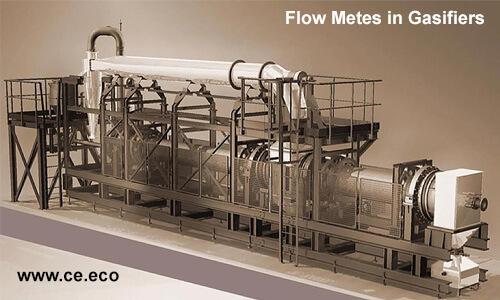
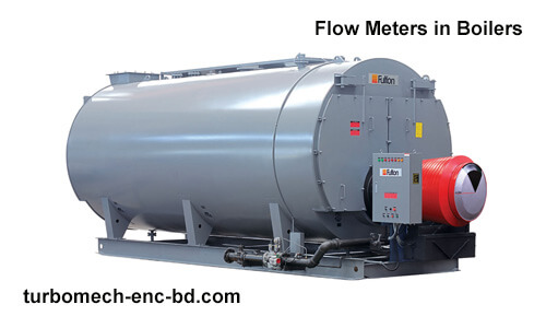
The term is usually used with measurement devices and combustion plants like boilers and gasifiers and is critical while choosing a flow meter.
Turndown ratio can be calculated in this way:
TR = Q (max) / Q (min)
Where
TR = Turndown Ratio
Q (max) = Maximum Flow
Q (min) = Minimum Flow
Example #1;
If a gas to be measured varies between 100,000 m3/day and 1,000,000 m3/day.
This specific application has a TR= 10:1.
If the flow meter had a maximum flow of 2,000,000 m3/day then the required turndown ratio (TR) would be 20:1
Note;
- Turndown Ratio is one of the variety of considerations while selecting or sourcing for a flow meter for your application
- TR of a flow meter is highly affected by the device's signal-to-noise ratio (S/N Ratio) which results from the fluid dynamics of the technology and the sort of sensor applied.
Typical turndown ratio of various meter types
Here we give you example for gas flow, and the same type are capable for liquid measurement, and they provide the same turndown ratio.
Keep in mind that flow meter producers give the turndown ratio for their devices—a flow meter may have a turndown ratio that varies from the following list .
- A Thermal Mass Flow Meter turndown ratio is 1000:1.
- An orifice plate meter practical turndown ratio is of 3:1.
- A Turbine Meter has a turndown ratio of 10:1.
- Rotary positive displacement meters turndown ratio varies based on producer and application between 10:1 and 80:1.
- Turndown ratio for Diaphragm meters is 80:1.
- Multipath ultrasonic meters have the turndown ratio of 50:1.
Recent Posts
-

Booster Pump Troubleshooting and Maintenance: How to Fix and Prevent Common Issues
1. Introduction Imagine turning on your faucet only to be greeted with a weak trickle of water when …22nd Apr 2025 -

Energy-Efficient Booster Pumps: Selection and Tips for Maximizing Performance
1. Introduction Imagine never having to deal with fluctuating water pressure, noisy pumps, or skyroc …19th Apr 2025 -

Booster Pumps for Sustainable Water Systems: Irrigation and Rainwater Harvesting Solutions
1. Introduction Water scarcity is no longer a distant threat—it’s a reality affecting millions …16th Apr 2025