
Differential Pressure Measurement Modules
In traditional differential pressure transmitters, both sides of a measuring diaphragm are exposed to the measuring medium. With common differential measuring ranges of 500 mbar and common mode pressures of up to 10 bar, a temporary interruption of either the high or low pressure could bring about a 20-fold overload on the diaphragm. Such an overload can only be absorbed with complex and expensive adaptations to the structural design, without which the transmitter could unavoidably be ruined.
Specialists have designed differential pressure measurement modules to minimize these risks.
Differential pressure transmitters function with two selected, encapsulated silicon pressure sensors. They supply their respective output signals to the inputs of a micro- processor: the microprocessor’s computing power is enough to remove all reproducible nonlinearities and temperature dependencies, as determined throughout calibration, via mathematical means.
Using this method, differential pressure transmitters acquire a total error band of better than ±0, 1%FS throughout broad temperature ranges.
The analog output signal from the module is up to date as many as 200 times per second, and a good dynamic reserve is available for next processing. the measuring variety for differential pressure measurements of this kind have to be about 20% of the common-mode pressure.
The mechanical connection between the main channel of the flow controller and the pressure sensors is implemented in each case with a capillary tube, which is also de-signed as a low-pass filter for pressure peaks. All the components that come into contact with the measuring medium (besides for the sealing rings) are manufactured from high-grade stainless steel.
Based on just three differential pressure transmitters with variant equipment, very last flow rate values of between 0, 9 l/h and 36 l/h can be gained, relying on the common-mode pressure. The measuring ranges are fine-tuned with the assist of special orifices incorporated into the flow channel; the focused difference between output pressure and input pressure is typically approximately 500 mbar.
Digital signal processing and individual sensor signals for output pressure and input pressure created extraordinary advantages; for example, these can be applied internally within the flow controller to figure out overloads, set limits or to implement other diagnostic functions. Moreover, throughout calibration of the flow rate estimation, the calibration data may be totally recharacterized withinside the processor of the differential pressure transmitter, thereby ensuing in an „end-to-end“ calibration of the flow controller, not just the pressure sensor.
Do You Need Help For Field Installation?
We have thought everything through, submit your request for an on-site support.
Do You Need More Solutions? Have a Look at Our Vast Applications
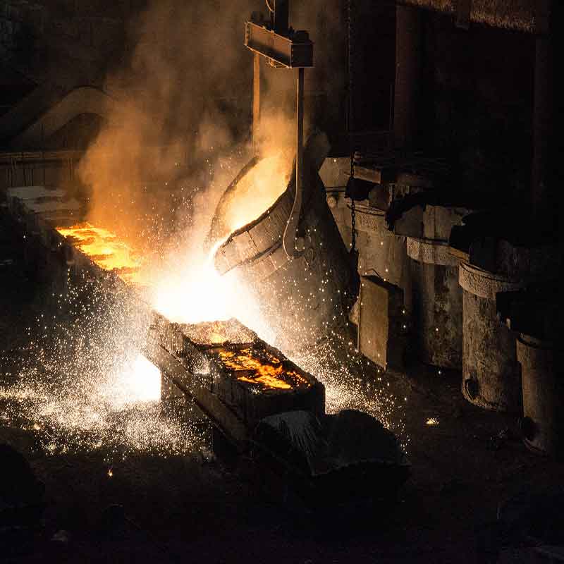
Flow Measurement in Metallurgy Industry: Orifice Flowmeters

Detecting the Position of Skid Carriers in Automotive Industry via Inductive High-Temperature Sensors

Special Remote Transmitters for Measuring Pressure and Temperature in Diamond Deposits
Related Products